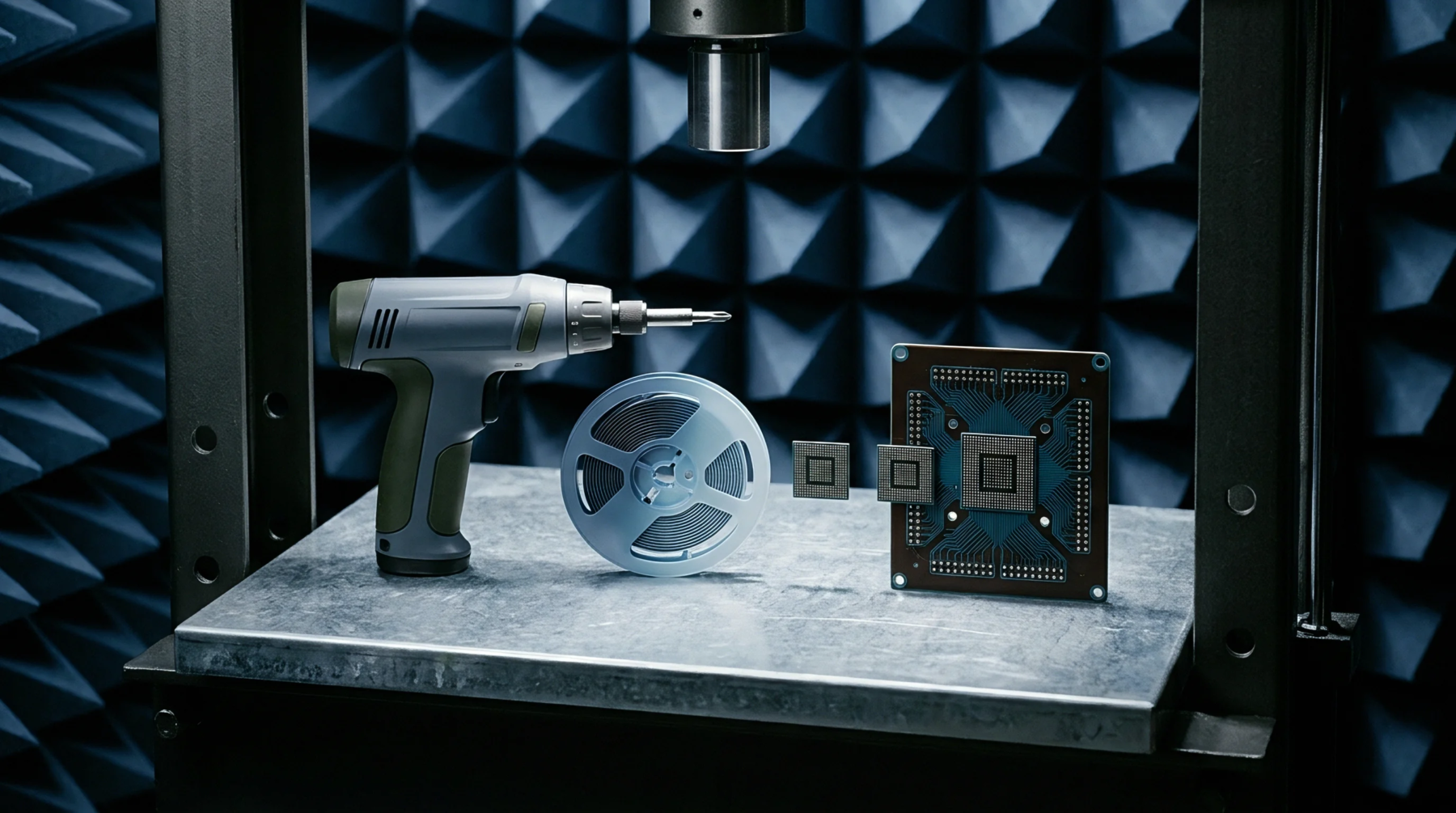
Measurement Process
An inspection technique measures electrical resistance across circuitry paths in real time during environmental or mechanical testing to detect transient failures. In reliability testing, continuous electrical monitoring tracks the resistance of solder joints and solder balls under thermal cycling or vibration. The measurement detects microsecond-long opens that occur during stress but close again when the stress is removed.
Degradation Signature
A stable circuit path maintains a constant resistance value, whereas a failing path shows rapid spikes or intermittent opens. Crack propagation in solder joints begins as a tiny fracture that opens only at the peaks of mechanical stress or at thermal extremes. Conventional static measurements at the end of a test cycle often fail to catch these defects because the joint settles back into a contacting state.
Through high-speed data acquisition, continuous electrical monitoring records these short-lived resistance events to identify the exact cycle when structural breakdown begins. It prevents false passes by recording every spike above a threshold such as one thousand ohms lasting for more than one microsecond.
Interconnect Quality
Workmanship standards such as IPC-9701 define the failure criteria based on consecutive resistance events to avoid false positives from electrical noise. If a joint exceeds the resistance threshold for ten consecutive cycles, it is classified as a failure. The continuous tracking provides the data required to calculate the fatigue life of solder alloys under specific stress profiles.
Circuit designers use these fatigue curves to optimize pad dimensions and trace routing for harsh environments.