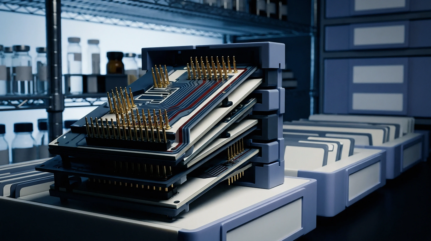
Fabrication Density
Copper circuitry width below one hundred micrometers defines the architectural boundary for this high density interconnect category. Engineers classify a fine-line pcb as a board populated with conductors and spaces tighter than the standard photolithography limits used in mass market production. Fabrication plants utilize direct imaging systems to achieve this resolution because traditional film masks distort under thermal expansion.
These systems reduce registration error by projecting patterns directly onto the photoresist surface.
Production Variance
Etch compensation serves as the primary tool to manage the loss of conductor width during chemical processing. Liquid chemistry removes copper from the sides of the traces as well as the top, a phenomenon known as undercut. Shop floor operators calculate an etch factor to adjust the artwork size before exposure so the final trace meets the design intent.
Advanced mappers monitor the spray pressure across the conveyor to ensure uniformity. Irregular spray distribution creates width gradients that cause impedance mismatches at the assembly stage. Any variation exceeding ten percent of the target trace width results in signal degradation for high speed designs.
Assembly Requirement
Solder mask registration creates the tightest constraint for surface mount components on this board type. Small pads require precise dam widths to prevent bridges between adjacent connections during reflow. Automated optical inspection verifies the clearance between the mask opening and the copper feature to ensure proper coverage.
Technicians prioritize the alignment of the stencil aperture to the copper pattern to guarantee optimal paste volume deposition. High precision placement equipment achieves the necessary accuracy for mounting components onto these miniaturized connection points. Reliability remains tied to the integrity of the trace geometry after thermal cycling.