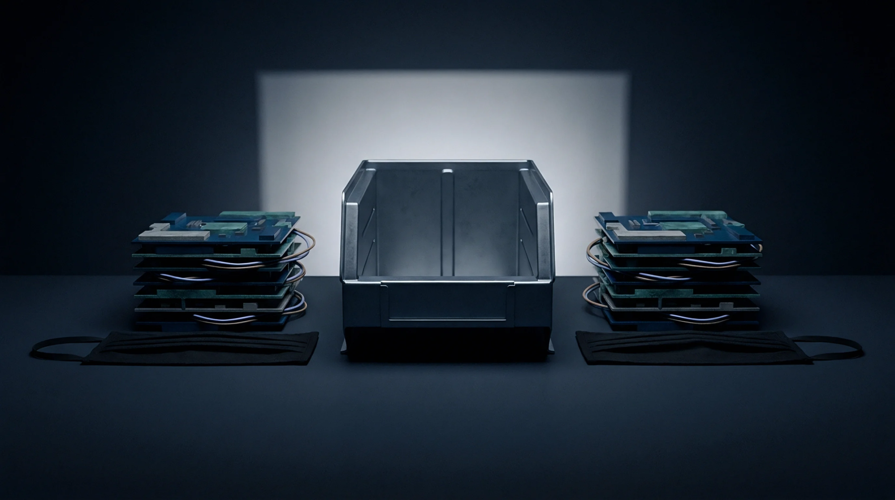
Multimaterial Architecture
Composite circuit laminations combine chemically distinct dielectric cores, prepregs and metal layers into a unified printed circuit board structure. In advanced electronics manufacturing, heterogeneous substrates integrate dissimilar materials such as ceramic-filled hydrocarbon high-frequency laminates, standard epoxy-glass FR-4 systems and polyimide flexible layers within a single multilayer stackup. The configuration reconciles disparate operational needs, providing high-speed radio-frequency transmission channels alongside conventional power and digital control circuits on one panel.
The definition applies to bonded dielectric combinations that undergo shared drilling, plating and lamination cycles, but it excludes multi-chip modules or packaging systems that join finished printed boards through mechanical fasteners, cables or solder joints.
Thermomechanical Disparity
Differing coefficient of thermal expansion values across adjacent material layers create severe shear stresses during press lamination and reflow soldering. Epoxy-glass cores typically expand at fourteen to seventeen parts per million per degree Celsius in the X and Y planes, whereas hydrocarbon-ceramic laminates or pure polytetrafluoroethylene layers expand at distinct rates. Glass transition temperature variations dictate that different layers soften at dissimilar times during heat exposure, which complicates press cure profiles.
Drill feeds and speeds must balance the dense ceramic fillers of high-frequency laminates with the soft, smear-prone resin of adjacent FR-4 cores. Desmear chemistries also face uneven challenges, because permanganate baths attack epoxy resins readily but fail to etch ceramic-filled matrices or fluoropolymers. Differential curing shrinkage induces panel warpage, copper trace strain and barrel crack susceptibility within plated through-holes.
Reliability Assessment
Fabrication quality is evaluated by IPC-TM-650 microsection inspection across lamination seams and through-hole barrels following six-cycle thermal stress conditioning. Visual inspections look for internal delamination, resin voids and copper-to-inner-layer barrel separation under IPC-A-600 Class 3 acceptance criteria. Shadow moire interferometry maps dynamic panel warpage across temperature profiles simulating lead-free reflow up to two hundred sixty degrees Celsius.
Micro-resistance measurements track daisy-chain nets through both substrate materials to catch micro-cracks induced by mismatched thermal expansion. Unbalanced designs fail arm’s length acceptance testing when panel bow and twist exceed zero point seven five percent or when interconnect resistance shifts by more than ten percent after thermal shock.