Quantifying Resin Flow Shear Dynamics in Multilayer Laminate Buildup Operations
Modelling resin squeeze flow shear kinetics during multilayer pressing prevents inner-layer trace swim and guarantees reliable dielectric clearance.
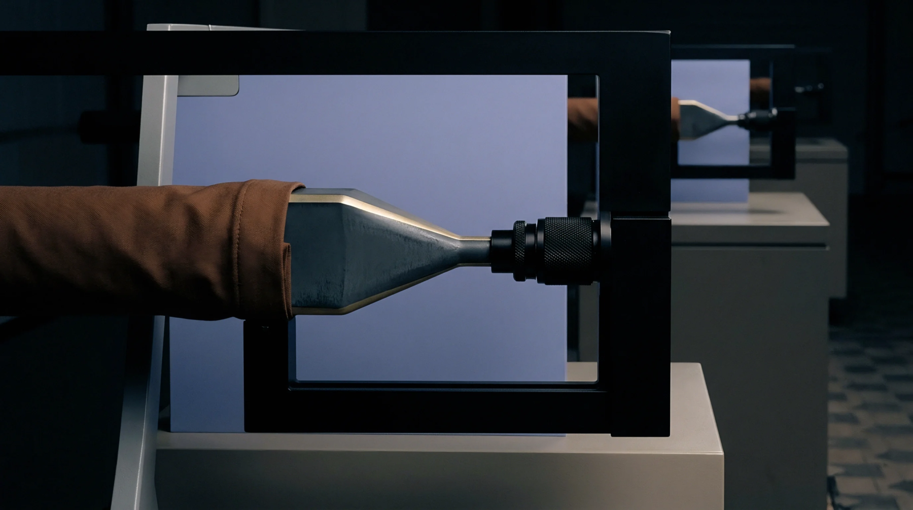
Mechanical tension acting parallel to a printed circuit board surface arises during rigid board routing and depanelization steps. Lateral shear stress defines the horizontal force per unit area that pulls discrete surface mount packages sideways across solder joint pads during flexure events. Board fabricators measure this friction threshold on destructive test coupons using shear tools mounted to calibrated load frames.
Production engineering relies on the resulting force values to verify that adhesive bonds withstand substrate deflection caused by automated depanelization routers. Solder joints endure maximum horizontal strain when adjacent board edges undergo severe deflection during final chassis installation. Excessive parallel force fractures intermetallic connection zones before component bodies crack under the load.
Testing protocols apply horizontal vector loads until joint separation occurs, recording the peak force in kilograms per millimeter. This boundary threshold applies strictly to surface mount configurations where components sit flat on copper lands without mechanical fasteners anchoring the housing. Pin through hole assemblies bypass this particular failure mode because their leads absorb bending vectors through elastic deformation rather than relying entirely on planar adhesion.
Solder paste volume and reflow profile temperature curves dictate the ultimate holding power against horizontal displacement.
Board level reliability depends entirely on maintaining strong interfacial adhesion between component terminations and printed circuit board pads. Automated assembly lines minimize lateral shear stress by programming milling paths that direct cutting blades away from populated areas during panel separation. Tool wear increases cutting resistance, which transfers higher physical vibration directly into nearby solder fillets during board routing operations.
Operators monitor spindle vibration signatures to detect dull routing bits before excessive lateral forces compromise fresh solder joints. Microscopic cross section analysis reveals microcracks forming along the heel of fillet joints when horizontal loads exceed established design margins. Automated optical inspection equipment flags misplaced components because off center placements reduce the surface area available to resist horizontal vector forces.
Lead free solder alloys possess higher yield strengths than traditional tin lead mixtures, altering how assemblies absorb parallel physical shocks during thermal cycling tests.
Destructive shear testing identifies weak interfacial bonds by pushing packaged components off test coupons at constant displacement rates. Laboratory technicians record peak force values alongside failure modes, distinguishing between pad cratering, bulk solder shearing and intermetallic fracture. Pad cratering occurs when excessive horizontal loads tear the copper foil and underlying resin away from the substrate instead of breaking the solder joint itself.
Substrate laminate quality directly influences whether the board material delaminates before solder connections fail under parallel strain. Manufacturing facilities track these destructive test metrics across production lots to verify incoming laminate and paste performance. Excessive board warp during secondary assembly processes increases vulnerability to lateral shear stress during final product housing installation.
Modelling resin squeeze flow shear kinetics during multilayer pressing prevents inner-layer trace swim and guarantees reliable dielectric clearance.
Expertise is a utility, not a secret. sentiention™ publishes its working knowledge as open reference: intelligence layer covering the materials it sources, the markets it enters, and the reference that serves both.