Reflow Behavior
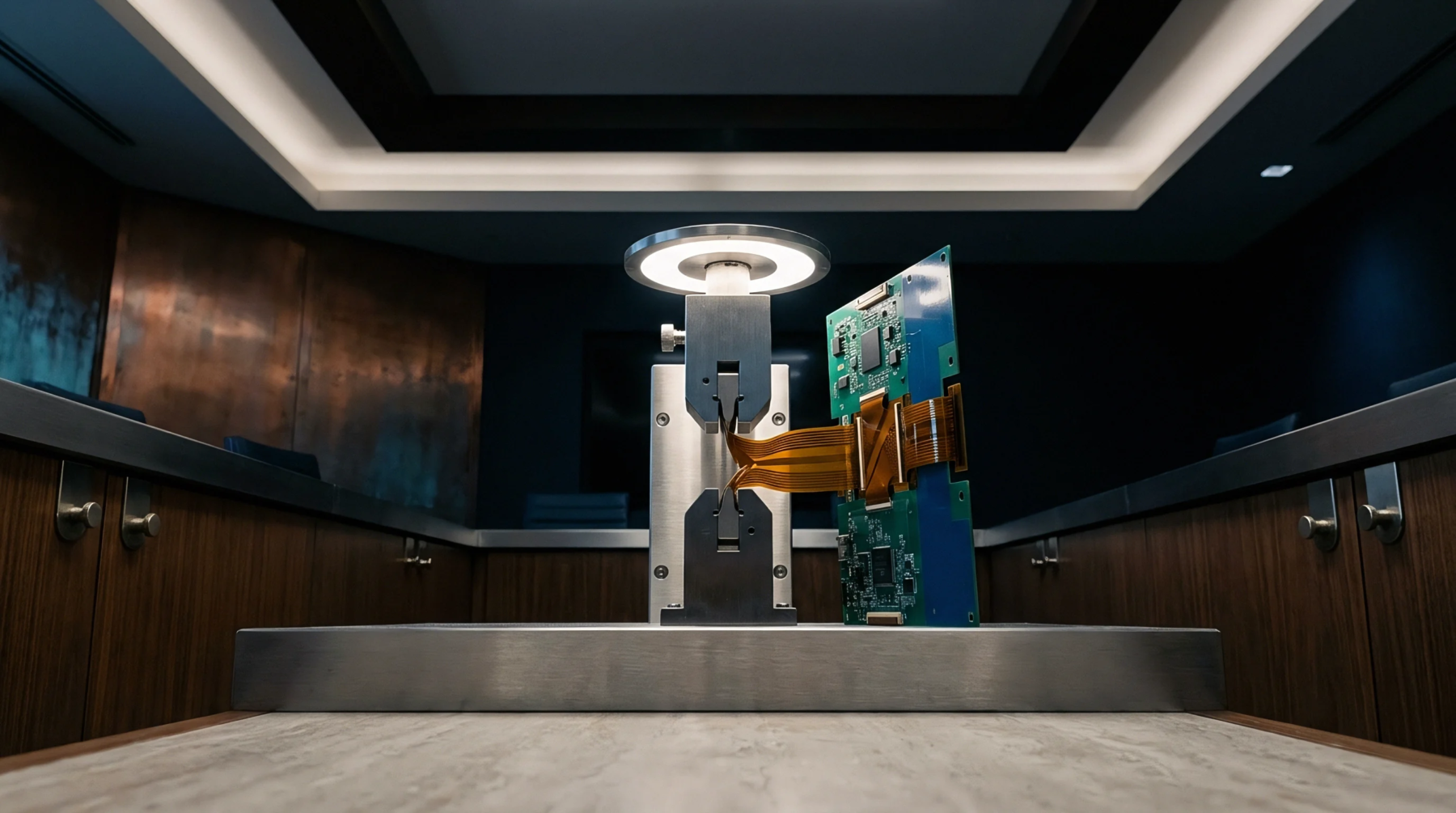
Surface mount assembly processes subject substrate materials and electronic packages to continuous temperature changes that induce out-of-plane shape changes. The dynamic warpage of printed circuit boards and ball grid array packages measures real-time profile distortion throughout the reflow soldering cycle. Mismatch between coefficients of thermal expansion across metallic traces, dielectric laminates and mold compounds drives these transient dimensional shifts.
Maximum distortion frequently occurs at peak reflow temperatures, causing open solder connections or bridged adjacent pads. Characterizing these dimensional changes prevents assembly defects during surface mount attachment.
Thermal Profile
Shadow moire interferometry and digital image correlation track vertical displacements across the component surface as temperature rises from ambient to reflow peak. As the board passes through the preheat zone, differential expansion between top and bottom copper layers creates a characteristic convex or concave bow. Glass transition of the underlying resin matrix sharply alters substrate stiffness, accelerating displacement rates above one hundred fifty degrees Celsius.
Cooling stages introduce additional stress as the solder alloy solidifies while the package continues to contract at varying rates across its structure. Excessive transient curvature causes corner solder balls to lift off signal pads before joint solidification finishes. Automated optical measurement systems record full-field three-dimensional displacement maps at fixed temperature increments to capture transient extremes.
Inspection Threshold
Component specification standards established by JEDEC dictate maximum allowable profile deviation at specific temperature benchmarks. Exceeding designated deformation limits causes coplanarity failure during automated pick-and-place placement or reflow.