Alignment Variance
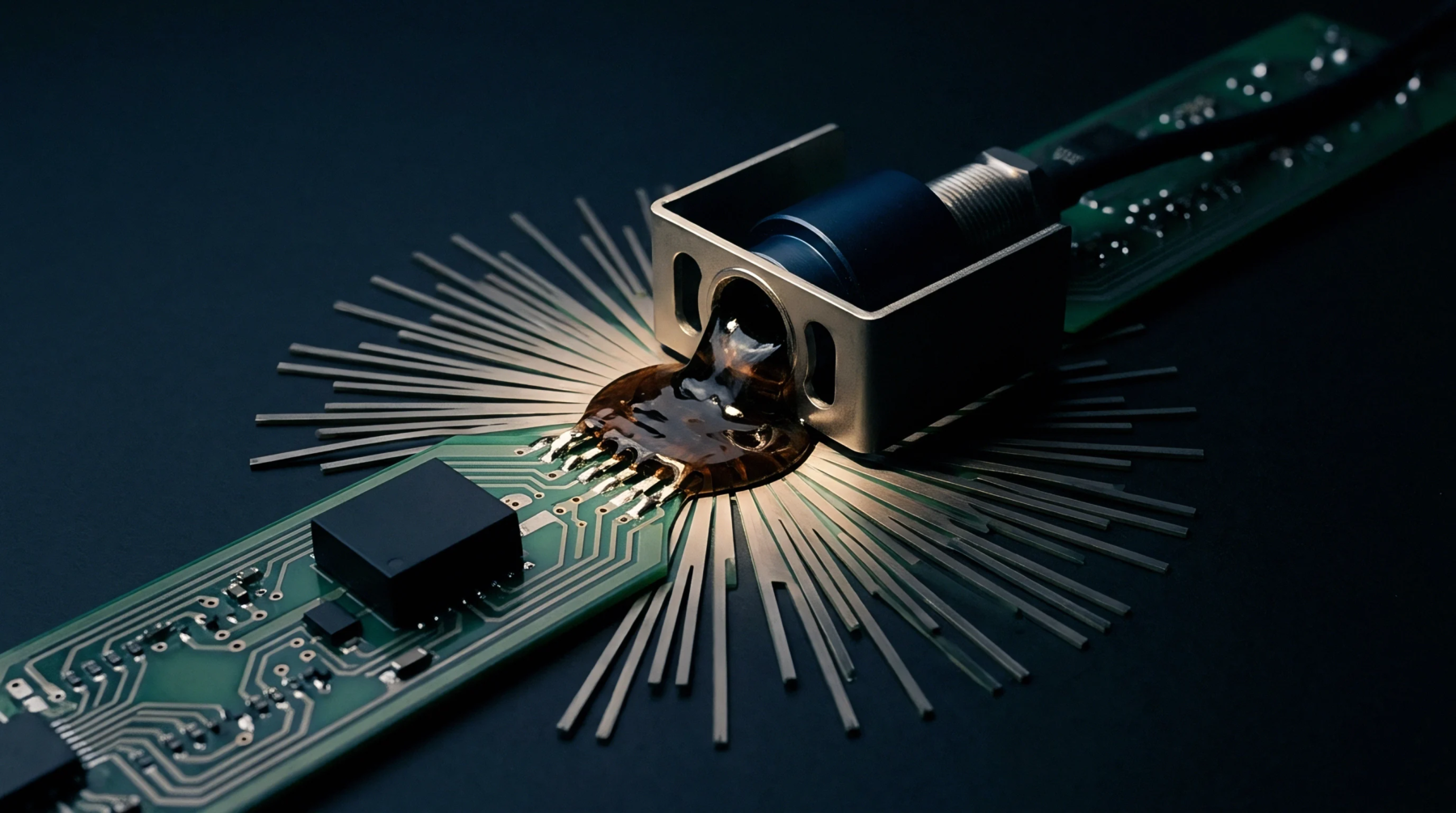
X-ray imaging performance stability relies on the spatial consistency of the electron beam source as it translates thermal energy into photon emission over continuous operational cycles. Focal spot drift occurs when the geometric center of the radiation source migrates from its calibrated axis during thermal equilibrium adjustments. This displacement happens as the anode and cathode assemblies expand under heat load.
Such movement introduces geometric blurring and parallax errors within high resolution inspection images. Mechanical stresses on the vacuum tube housing create additional positional instability. System controllers adjust beam steering magnets to counteract these deviations once the tube reaches a steady thermal state.
Regular verification procedures involve scanning a reference target to quantify positional error against fixed coordinate markers.
Thermal Correction
Precise beam positioning prevents artifacts in automated solder joint analysis. Constant monitoring of anode temperature allows firmware to compute real time offsets for the deflection coils. These coils steer electrons back toward the target center when sensor data confirms internal expansion.
Hardware designers mitigate base line movement by selecting materials with low expansion coefficients for the internal tube support structure. Forced air cooling helps maintain the tube skin temperature within a narrow band. High power X-ray sources require active feedback loops to maintain sharpness during long scanning sessions.
Stable beam geometry reduces the necessity for repeated system recalibration during production shifts. Vacuum integrity plays a role in how heat dissipates from the target surface area. Improper mounting of the tube results in structural load paths that exacerbate the shift.
Sensors placed near the focal point provide the raw data required for drift compensation algorithms.
Operational Boundary
Performance criteria define the maximum allowable deviation before image quality drops below the acceptable standard for a specific circuit density. Tolerances depend on the magnification factor of the imaging system and the expected pitch of the components being inspected. Deviation exceeding these predefined thresholds indicates either a failing cooling component or a structural defect within the tube mount.
Periodic verification maintains the validity of the measurement system. Internal hardware degradation eventually limits the effectiveness of software based correction methods. Accurate geometry maintenance dictates the reliability of the entire inspection process.