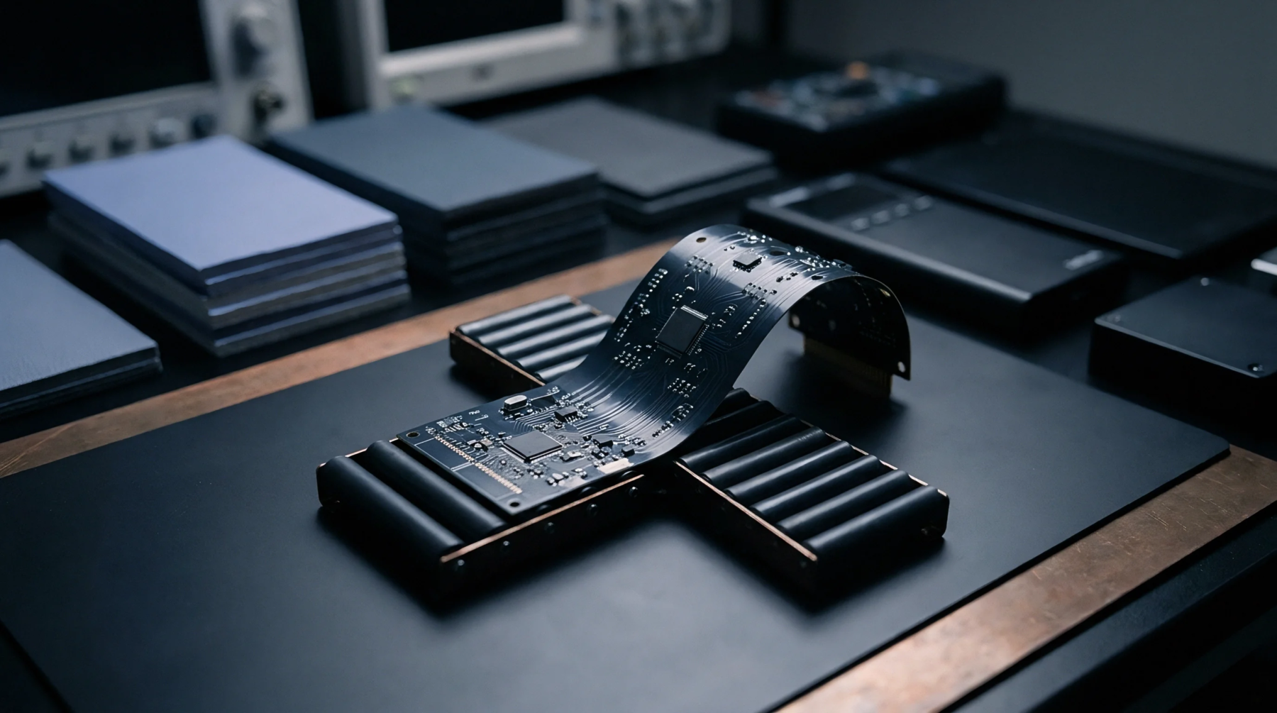
Layout Strategy
Design techniques for flexible electronics aim to minimize the mechanical stress applied to conductive copper layers during bending. Neutral axis trace positioning places the copper layer at the center of the stack where compressive and tensile forces cancel out. This location represents the plane of zero strain within the material cross section.
Strain Reduction
Bending a laminate causes the outer surface to stretch and the inner surface to compress. By utilizing neutral axis trace positioning, the copper is shielded from these extremes, which reduces the risk of work hardening or fracturing. The effectiveness of this technique relies on a balanced stackup where the thickness and modulus of the materials above and below the copper are identical.
Trace Alignment
Achieving the correct placement requires a precise calculation of the mechanical center of the entire assembly. For a simple two layer circuit, neutral axis trace positioning is managed by selecting coverlay and base films of equal thickness. In more complex multi layer constructions, the presence of stiffeners or pressure sensitive adhesives shifts the zero strain plane away from the physical center.
Engineers use software models to verify that the most sensitive traces remain in the low strain region. This approach is standard in the manufacturing of hard disk drive cables and foldable display connections where millions of flex cycles are expected. Flexibility requires this balance.