Cross Line Optical Inspection Machine Calibration Fundamentals
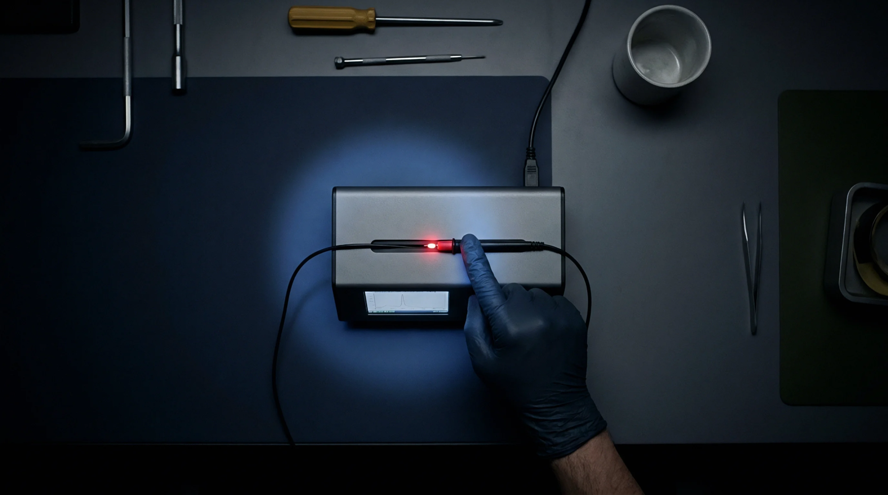
Optical calibration translates reticle pixel grids into true spatial coordinates, establishing assembly yield baselines before boards enter production lines.
The apparent shift in the relative position of an object when viewed from different angles or off-center optical axes introduces perspective error into machine vision environments. Standard optical lenses produce optical parallax because light rays diverge from the target toward the camera lens entrance pupil in an angular cone. In printed circuit board inspection, this geometry causes tall components situated away from the central optical axis to appear tilted outward toward the edges of the image frame.
Subsurface features, such as solder pads or circuit traces positioned underneath the bodies of large tall components, become obscured from view. Similarly, the top surfaces of components appear displaced relative to their ground-level footprints, confounding two-dimensional dimensional calculations. The effect scales with the height of the physical object, the focal length of the objective lens and the lateral distance between the inspected feature and the principal optical axis of the sensor.
Ray paths diverging through standard photographic and entocentric lenses generate magnification changes proportional to object distance, creating severe perspective distortion across three-dimensional scenes. Features situated closer to the lens appear larger than identical features located further down in the z-axis plane. In assembled board processing, a dual-in-line package, an electrolytic capacitor or a tall connector viewed off-axis casts an apparent perspective displacement over adjacent circuit traces.
Automated edge detection algorithms measure the top boundary of an off-axis component lead and misinterpret its coordinate position relative to the underlying surface-mount land, registering an apparent placement error that does not exist in physical reality. Parallax also produces severe occlusion zones, casting visual blind spots behind tall structures that prevent the verification of adjacent solder fillets, polarity marks or tiny passive decoupling capacitors. Installing telecentric lenses suppresses this phenomenon by accepting only light rays that run parallel to the mechanical optical axis, eliminating perspective shifts across the entire depth of field.
Automated optical inspection units running standard optics encounter elevated false failure rates when parallax distorts component geometries near field edges. When calculating lead-to-pad alignment on high-pin-count devices, such as quad flat packages, perspective tilt causes corner pins to appear shifted outward, violating registration tolerances. Inspection software must incorporate complex three-dimensional parallax compensation algorithms, skewing detection regions outward as a function of radial distance from the image center, which increases computation times and reduces measurement certainty.
Solder meniscus evaluation on surface mount gull-wing leads suffers when side perspectives alter the apparent slope and reflection angle of solder fillets. Solder paste inspection systems completely avoid standard optics for this reason, relying instead on structured light projection or telecentric paths to prevent the perspective distortion of paste brick height. Controlling perspective errors eliminates artificial misalignment calls, preserves correct pad inspection visibility and maintains measurement accuracy across multi-height circuit assemblies.
Optical calibration translates reticle pixel grids into true spatial coordinates, establishing assembly yield baselines before boards enter production lines.
Expertise is a utility, not a secret. sentiention™ publishes its working knowledge as open reference: intelligence layer covering the materials it sources, the markets it enters, and the reference that serves both.