Alignment Measurement
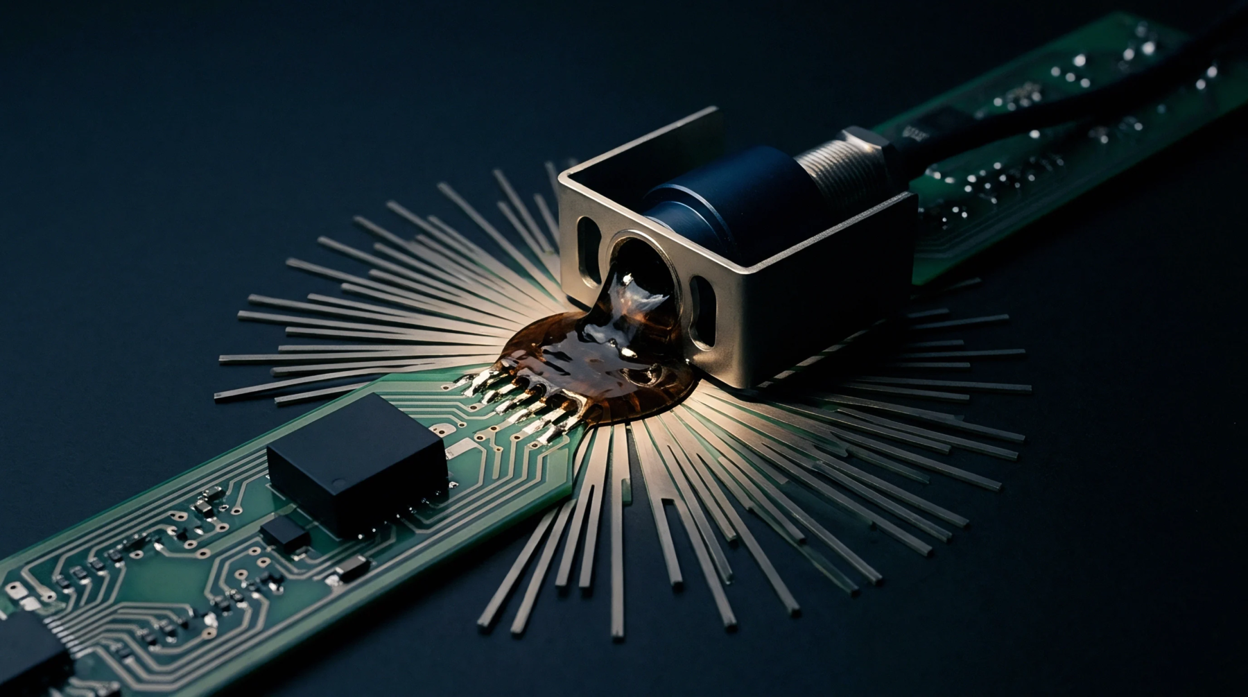
Vertical optical monitoring evaluates the planar orientation and lateral placement of surface mounted components upon a printed circuit board assembly. This top-down optical inspection process verifies that each lead aligns with its corresponding solder pad before the reflow cycle occurs. Algorithms identify positional shifts by comparing current capture geometry against preprogrammed coordinate data derived from original design files.
Deviations exceeding defined tolerance limits trigger an alert for manual verification or automated rework.
Imaging Mechanism
High resolution digital cameras mounted on a gantry system move along an XY plane to scan the surface of the populated substrate. Programmable lighting arrays illuminate the assembly from multiple angles to highlight component edges and solder paste deposits. Software processes these light variations to distinguish between metallic leads and dark substrate material.
Such hardware configurations enable the system to detect missing parts or rotated packages that sit outside acceptable mounting parameters. Rapid processing sequences allow for high throughput evaluation during the manufacturing run.
Defect Resolution
Automated optical capture identifies misplaced chips by checking the centroid position against the board layout reference. Solder bridges form when adjacent pads touch during placement and this specific geometry creates high contrast profiles during the scanning stage. Incorrect polarities show up as asymmetrical lead patterns compared to the master library file for each component type.
Accurate detection of these conditions prevents electrical shorts that would otherwise demand costly de-soldering and replacement operations downstream. Functional performance failures correlate directly with the precision of these early stage visual verification checks.