Node Architecture
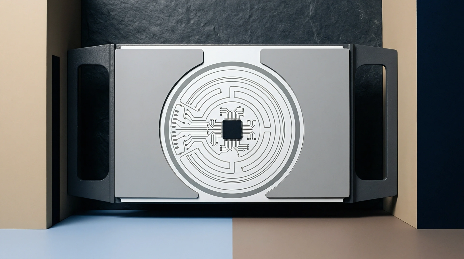
Hardware testing relies on a boundary scan cell to observe and control digital logic states at integrated circuit pins without physical probe access. This elemental circuit structure acts as a shift register stage connected directly to a system pin or internal core signal path. Test engineers configure the architecture during circuit board design to form serial chains across complex integrated circuits.
Manufacturing lines activate these chains to verify board level interconnections and detect solder bridging defects or open circuits on bare printed circuit boards after surface mount technology placement.
Electrical Control
Voltage propagation through the serial register depends entirely on clock signals and mode select inputs managed by a central test access port controller. Digital test equipment shifts specific bit patterns into the chain to force specific logic levels onto output pins while capturing responses from adjacent input nodes. Signal integrity within the assembly process dictates that parasitic capacitance along the internal routing path must remain low enough to prevent data corruption during high frequency shifting operations.
Automated optical inspection machinery and in-circuit testers operate downstream from this register verification to isolate intermittent electrical faults that escape digital test vectors.
Impedance Boundary
Operating parameters for the logic capture stage are strictly bounded by the maximum clock frequency specified in standard test architecture protocols. Excessive clock skew across a dense printed circuit board assembly degrades the timing margin of the shift register and triggers false failure flags during parametric testing. Board fabrication facilities must maintain trace impedance tolerances within established limits to prevent reflection interference from distorting the serial test data stream.
Signal degradation beyond the specified threshold halts the boundary scan test sequence and invalidates the assembly verification report.