Contact Geometry
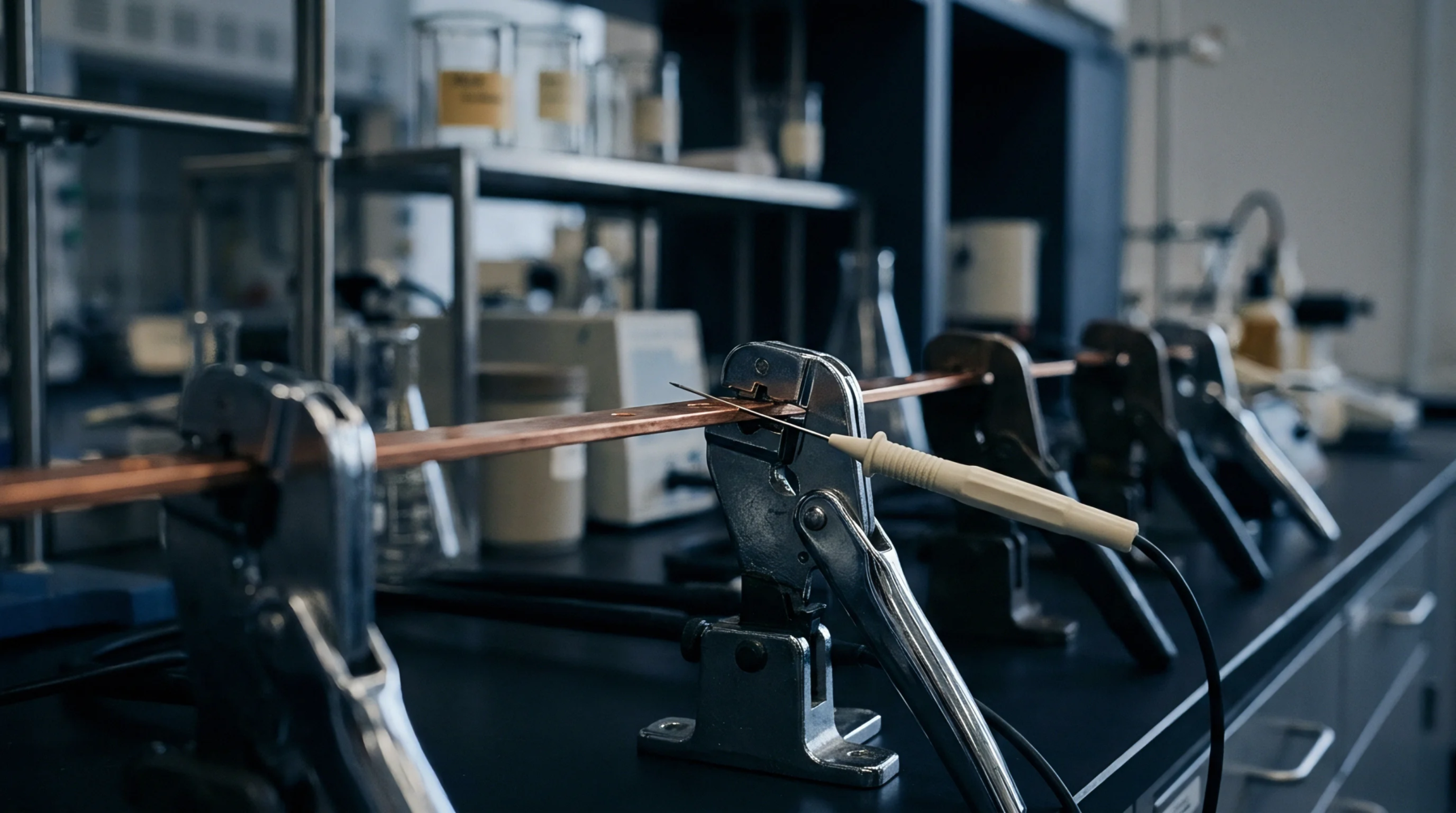
Metallic interfaces provide the conductive path for spring-loaded pins during in-circuit testing. A crown probe tip features multiple sharp points arranged in a circular or hexagonal pattern to penetrate surface contamination and oxidation on solder joints or pads. These geometric protrusions create low-resistance electrical connections by piercing the thin oxide layer that frequently forms on tin or lead-free solder surfaces.
Increased contact pressure at each individual point facilitates stable signal transmission for automated test equipment.
Interface Mechanics
Geometric configuration determines the reliability of the physical connection during high-volume production cycles. A crown probe tip maintains contact across uneven surfaces by distributing mechanical force through its distinct teeth, which prevents the pin from sliding off small test points. Hardened tool steel or beryllium copper provides the structural rigidity necessary to withstand repeated actuation against rigid substrates.
Mechanical wear eventually dulls these points, leading to inconsistent measurement readings and open circuits.
Deposition Constraints
Fabrication parameters limit the application of these components to specific pad sizes and board layouts. A crown probe tip requires precise alignment to ensure all teeth make simultaneous contact with the target landing area, as unequal distribution causes localized board damage or false test failures. Alignment software compensates for moderate positional offsets by centering the tool over the intended copper feature during the touchdown sequence.
Proper maintenance schedules prevent debris buildup within the crown geometry which otherwise degrades the electrical signal integrity over prolonged usage.