Operational Definition
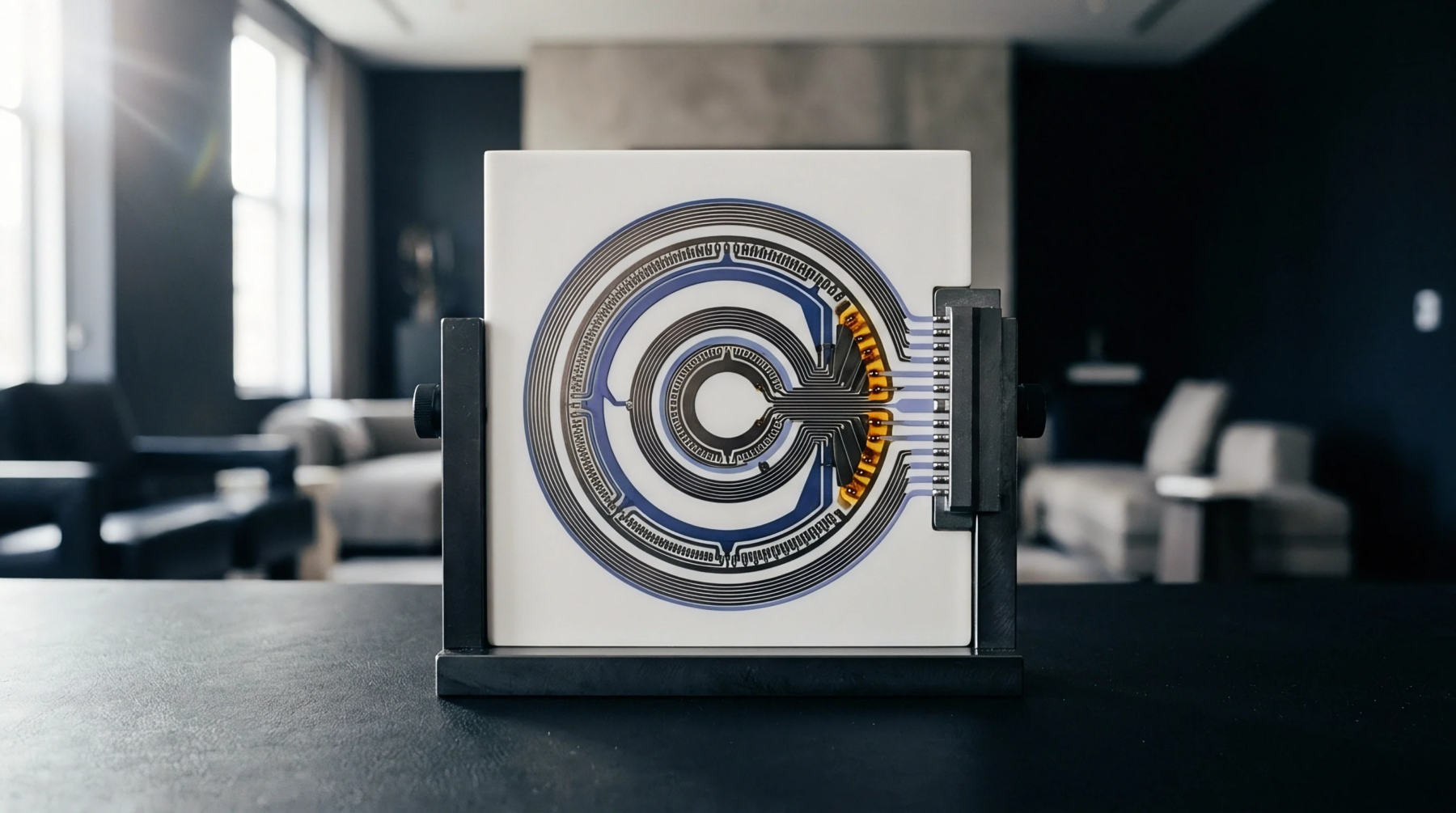
Circuit board assembly verification requires measuring minute voltage variations across matched signal traces, a capability delivered through differential amplification. This electronic processing method subtracts unwanted common mode noise picked up by parallel conductors during transmission while doubling the valid amplitude of the actual data signal. Production testing equipment relies on this dual input topology to isolate true operating voltages from background electromagnetic interference generated by adjacent switching regulators on densely populated multilayer panels.
Acceptance limits depend strictly on the common mode rejection ratio measured during automated optical and electrical probing stages. Unwanted signal distortion occurs when component tolerances introduce impedance mismatches between the positive and negative input channels before the signal reaches the integrated operational amplifier package.
Impedance Matching
Automated surface mount placement machines deposit passive resistors alongside active semiconductor components with tight parametric tolerances to preserve signal symmetry across the differential pair. Deviations in solder paste volume during stencil printing alter the parasitic capacitance of individual joints, which degrades high frequency performance and generates phase errors. Oscilloscope measurements capture these timing skews during final functional testing of completed electronic modules.
Thermal cycling tests expose marginal solder joints that eventually drift in resistance value over extended operational lifespans. Manufacturing technicians verify circuit symmetry by injecting test frequencies into the bare board prior to final enclosure integration.
Rejection Boundary
Practical circuit designs face physical limitations when differential amplification encounters extremely high frequencies or severe ground potential differences between remote subassemblies. Parasitic inductance within the printed circuit board traces restricts the upper frequency cutoff where common mode suppression remains effective against radiated interference. Component aging alters transistor bias points inside the integrated circuit, causing thermal drift that gradually reduces the direct current common mode rejection capability over years of continuous operation.
Shielding enclosures prevent external radio frequency interference from saturating the input stages during deployment in harsh industrial environments. Proper circuit grounding strategies prevent ground loops from overwhelming the balanced input architecture.