Core Architecture
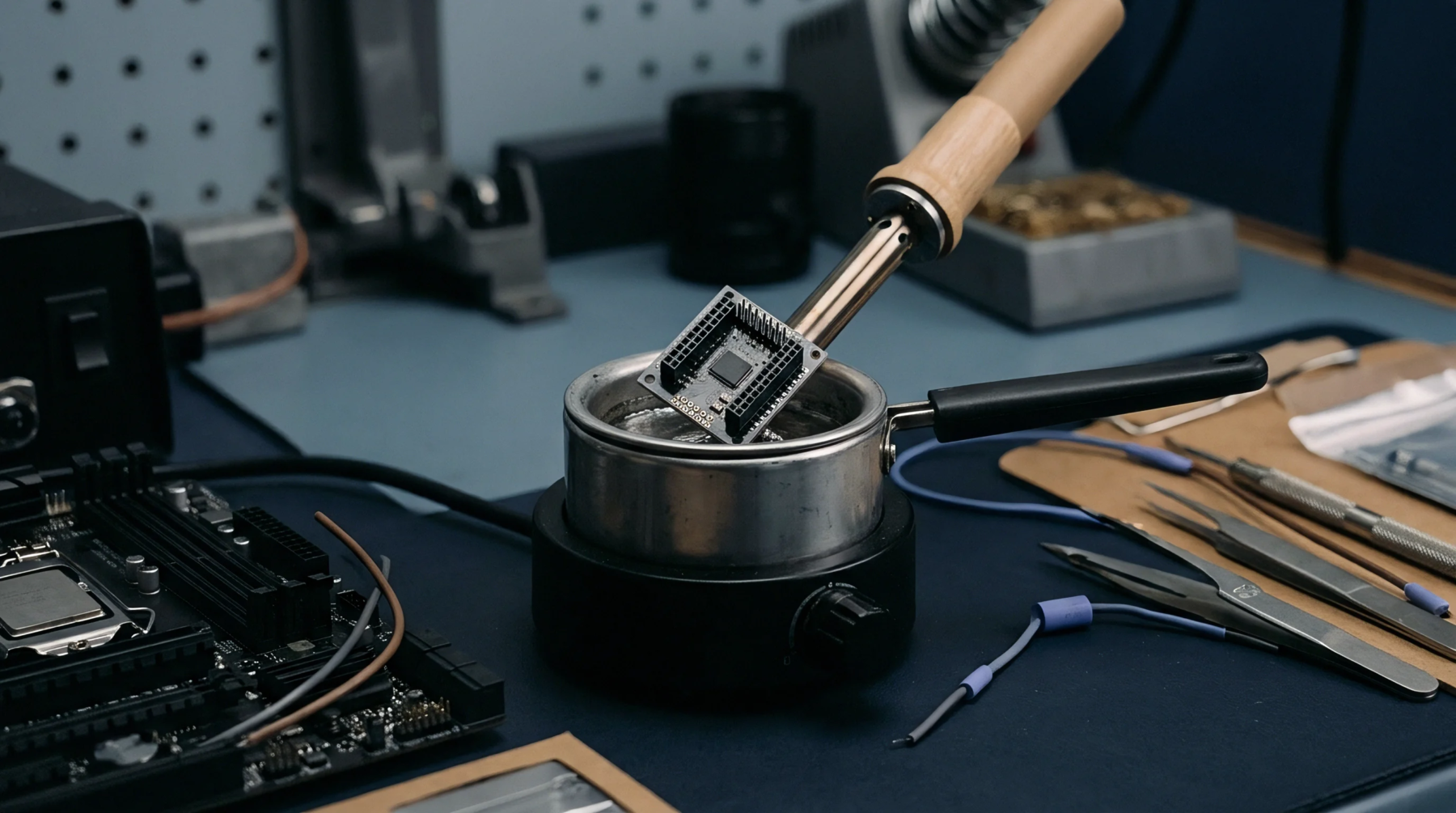
Dielectric buildup defines the engineered base material that carries ultra-dense circuitry through sequential lamination cycles. An hdi substrate employs microvias, sequential build up layers, and fine line copper etching to shrink component footprints inside mobile and computing hardware. Laser drilling creates blind and buried holes down to fifty micrometers in diameter, permitting signal routing beneath dense ball grid array packages where mechanical drills fail.
Inner layer core materials typically consist of reinforced glass epoxy resin with specific low dielectric constant values to minimize signal propagation delay at high frequencies. Dielectric thickness between adjacent copper planes decreases significantly compared to standard multilayer boards, raising capacitance coupling risks while simultaneously shortening return current loops. Copper foil weights drop to half-ounce or quarter-ounce thicknesses before plating to preserve fine line resolution during etching operations.
Thermal Defect
Microvia barrel cracking emerges during assembly reflow soldering cycles due to mismatched coefficients of thermal expansion between copper plating and surrounding dielectric resin. Plating thickness inside blind holes must maintain a minimum twenty-five micrometer barrel coverage to withstand high thermal stress without fracturing under z-axis expansion forces. Excessive moisture absorption inside resin matrices before thermal exposure leads to delamination between sequential build up layers, producing open circuits during surface mount placement.
Inspection personnel deploy cross-sectional microsectioning alongside scanning acoustic microscopy to detect microscopic voids hidden beneath solder mask layers before board release. Thermal shock testing regimes cycle finished parts between minus sixty degrees Celsius and one hundred twenty-five degrees Celsius to expose weak copper-to-copper plating interfaces.
Electrical Verification
Automated test equipment measures characteristic impedance values across finished signal traces to verify signal integrity compliance against engineered design tolerances. Impedance control relies on precise dielectric height maintenance and copper width etching consistency across every sequential lamination layer. Time domain reflectometry isolates discontinuities caused by acid trap etching defects or incomplete copper fill inside stacked microvia structures.
High-potential voltage testing applies DC potentials exceeding normal operating levels to screen for dielectric breakdown faults between adjacent conductive layers. Final electrical screening confirms continuity across high-density interconnect networks without inducing permanent mechanical strain on fragile internal copper connections.