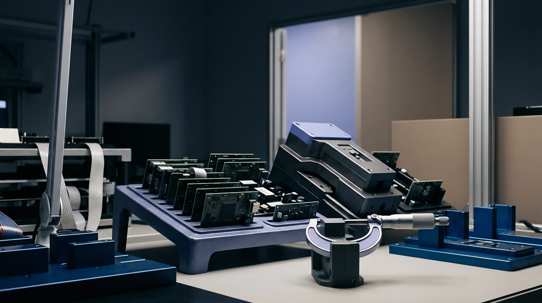
Mechanical Alignment
Automated test fixtures secure circuit assemblies against spring-loaded probe fields using rigid vertical push pins installed in the upper vacuum or mechanical lid. Proper hold-down rod positioning prevents board flexure, trace cracking, pad delamination and unseated contact pins during in-circuit electrical testing. Fixture designers calculate contact locations across unpopulated substrate areas to balance downwards pressing force against probe resistance.
Misaligned push rods transmit bending moments into glass epoxy laminates, causing internal copper trace fracturing or solder joint damage.
Stress Distribution
Uniform pressure application across the printed circuit board assembly neutralizes localized spring force concentrations generated by dense test pin fields. When hold-down rod positioning leaves wide gaps between support points, actuation forces bend the substrate downward under mechanical strain. Strain gauge measurements verify that localized strain levels remain below critical thresholds specified in IPC-J-STD-001 during fixture closure.
Component Clearance
Vertical push rods must avoid surface-mount components, tall electrolytic capacitors, heat sinks and sensitive optical sensors mounted on the top assembly side. Clearance calculations incorporate manufacturing tolerances of the fixture lid, push rod tip cushions and component height variations across production lots. Rubber tips or molded static-dissipative plastic endcaps protect nearby components from mechanical abrasion during high-volume testing cycles.