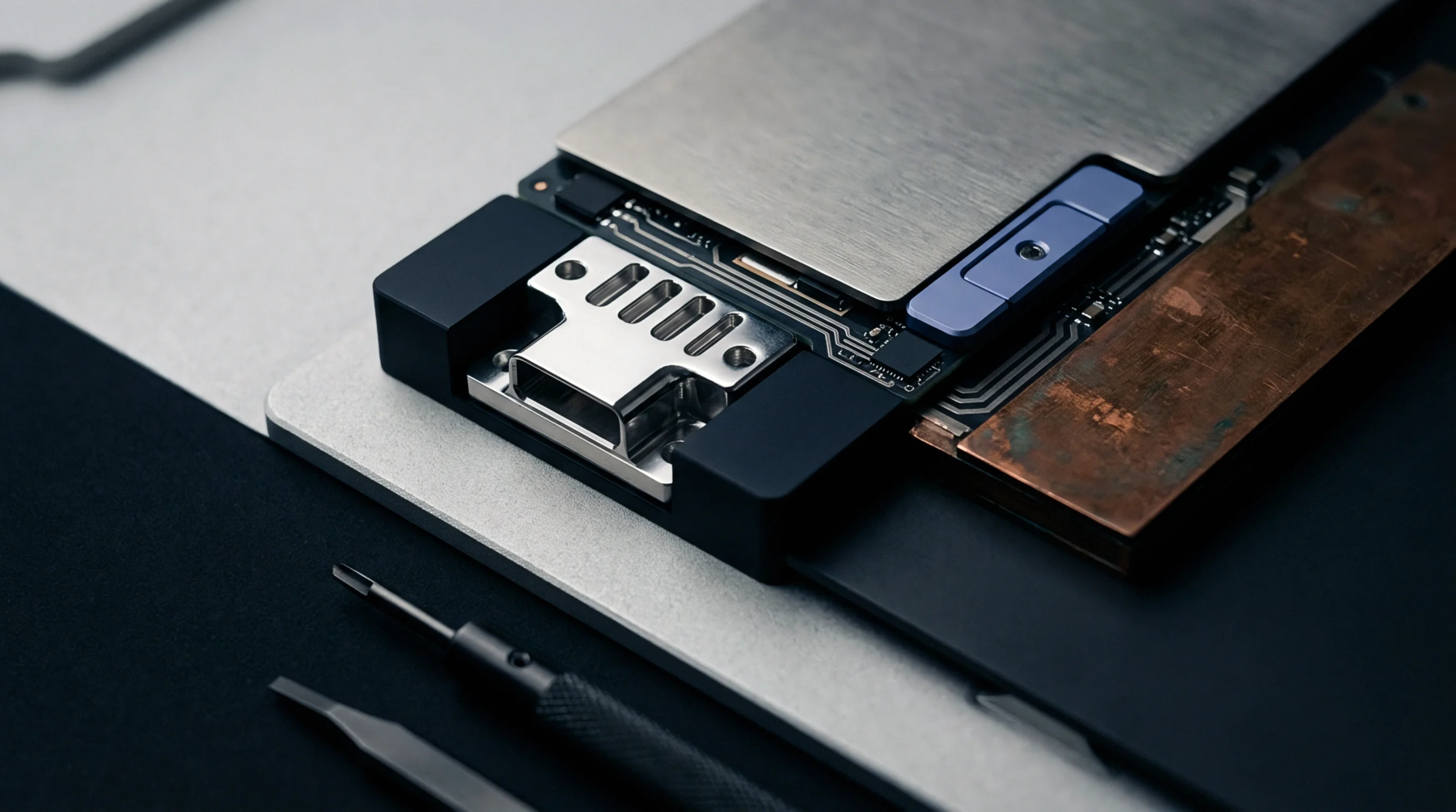
Copper Thickness
Internal metal foil weight forms the baseline conductive pathway buried beneath subsequent dielectric prepreg layers inside a multi-layer printed circuit board stackup. Standard ounce per square foot ratings govern innerlayer copper selection, establishing current-carrying capacity and thermal distribution profiles across specific board regions. Fabricators etch specific geometric trace patterns into this metallic sheet during subtractive processing sequences prior to the final pressing cycle.
Post-etch automated optical inspection systems scan these transferred circuit topologies for shorts, opens, and dimensional anomalies before the laminate stack reaches the hot press.
Etching Allowance
Undercut compensation factors dictate the necessary photographic mask adjustments applied during layout generation to account for chemical acid lateral erosion. Chemical etchants consume copper vertically while simultaneously chewing horizontally beneath the photoresist overhang, reducing trace cross-sectional area if uncompensated. Acid spray pressures, etchant temperature, and cupric chloride concentration gradients determine the exact etch factor ratio applied to innerlayer copper conductors.
Designers must calculate trace width biases based on finished copper weight classes, ensuring final line geometries match electrical impedance targets after complete material removal.
Stackup Symmetry
Balanced mechanical construction protocols prevent thermal warping by requiring identical copper weight distribution on opposite sides of the neutral axis during high temperature lamination. Press operators pair matching foil masses across the center dielectric core, equalizing resin flow and residual mechanical stresses during the pressing cycle. Unbalanced innerlayer copper distribution generates excessive board bow and twist, compromising subsequent surface mount component placement accuracy and solder joint integrity.