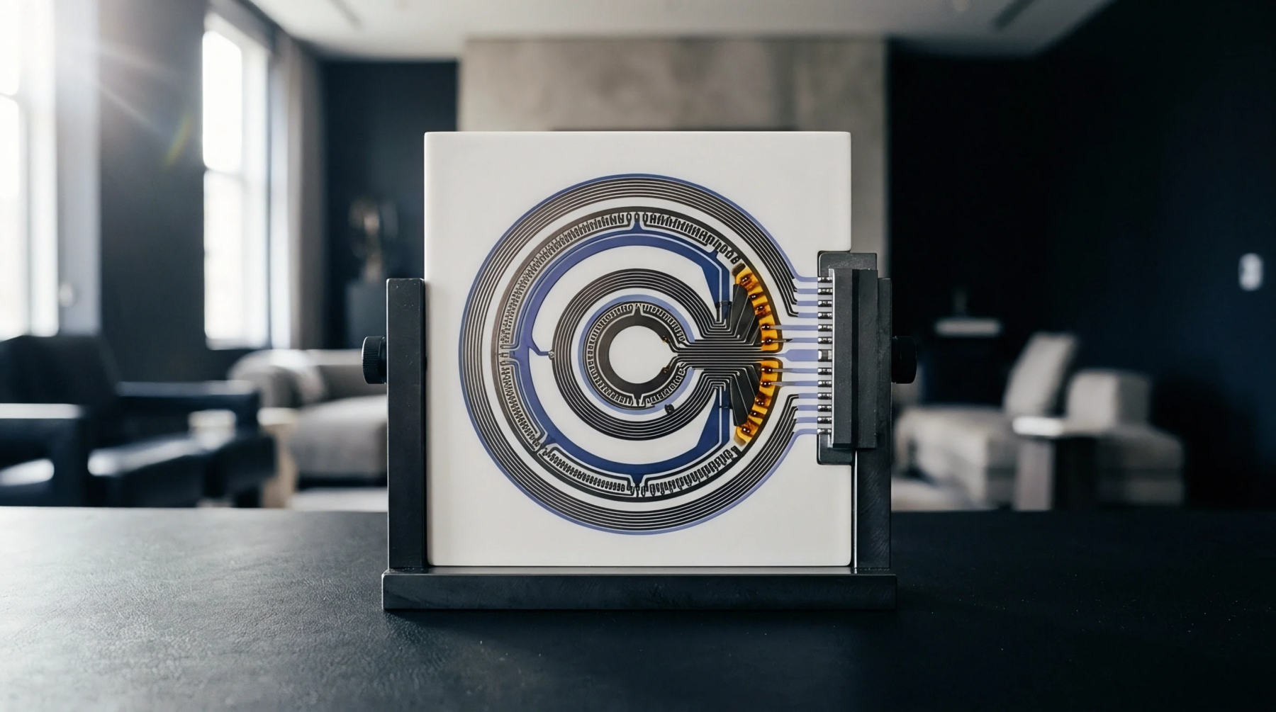
Test Engine
Boundary-scan testing utilizes a dedicated hardware block within integrated circuits to access internal signals without physical test probes. This logic block is governed by a jtag tap controller, which manages the test data and instruction registers via a four-wire or five-wire serial interface. The controller operates in synchrony with the test clock to transition through a standard sequence of internal states.
By providing this direct access, the block allows board manufacturers to test complex printed circuit boards that have limited physical test points.
State Machine
The internal architecture of the device relies on a sixteen-state finite state machine controlled by a single test mode select line. During board testing, the jtag tap controller interprets transitions on this select line to capture data, shift test patterns, and update instruction registers. Data flows into the device through the test data input pin and is shifted out through the test data output pin.
This serial chain enables the execution of built-in self-tests and boundary scan routines across multiple chips on the board.
Board Diagnosis
In circuit board assembly, the boundary-scan chain connects multiple integrated circuits in a single path. By controlling the jtag tap controller of each chip, test systems can verify the electrical continuity of the solder joints between high-density components. This test is critical for ball grid arrays where the pins are hidden from visual inspection or manual probing.
When the test fails, the controller provides detailed diagnosis by pinpointing the exact pin and trace that has an open circuit or a short to ground. Test developers write specific boundary-scan description language files for each component to describe how the controller registers are mapped, enabling the test hardware to automate the generation of diagnostic vectors during high-volume production.