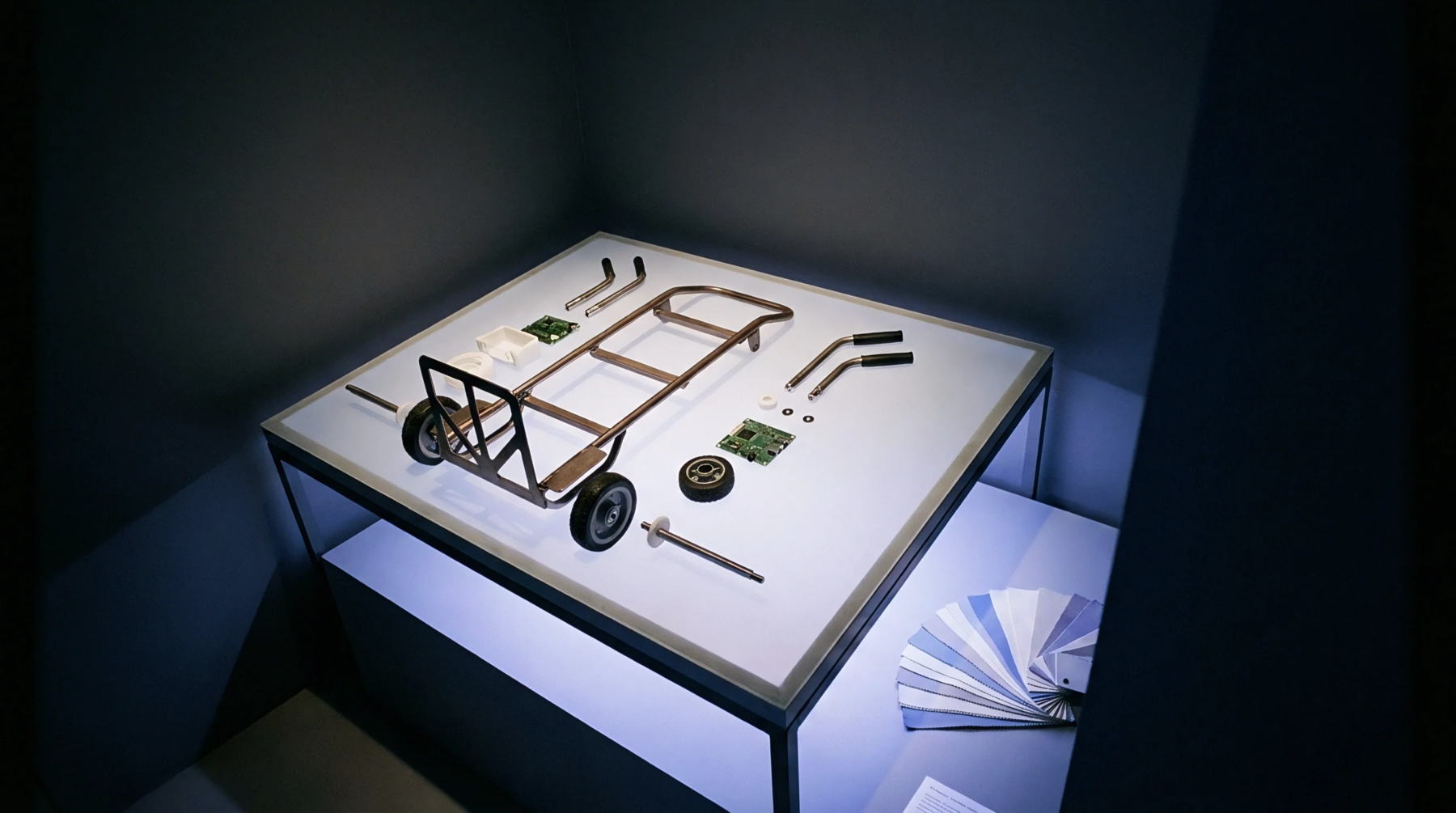
How a Printed Circuit Board Is Built Layer by Layer
Multilayer PCB fabrication laminates etched copper cores and prepreg under heat and vacuum, creating vertical interconnects through precision drilling and copper electroplating.
Photochemical and photothermal material removal directs focused ultraviolet or infrared energy onto copper clad laminates to vaporise dielectric resin and form blind openings connecting outer and inner circuit layers. High energy photon emission breaks polymer chains while concurrent thermal action expels debris from the small cavity before subsequent metallisation steps. Ultraviolet output wavelengths typically range around three hundred fifty five nanometres, providing adequate photon density to cleave organic bonds cleanly without excessive thermal stress on surrounding glass reinforcement strands.
Operators program specific pulse frequency parameters to govern energy delivery, preventing excessive carbonisation along internal hole walls which otherwise degrades subsequent electroless copper adhesion during wet processing. Production facilities run optical inspection routines immediately after processing to detect residual dielectric films or resin smear at the hole bottom, because inadequate cleaning prevents proper copper nucleation during chemical deposition. Process engineers monitor beam diameter variation across the scan field because optical drift alters finished via dimensions beyond acceptable manufacturing tolerances defined in rigid multilayer board specifications.
Subsurface thermal degradation occurs when excessive laser fluence damages surrounding dielectric materials during rapid polymer vaporisation. Excessive local heating causes localized resin detachment from glass reinforcement bundles, creating microscopic voids that compromise long term thermal reliability under reflow soldering conditions. Manufacturers measure this specific damage through cross sectional metallisation analysis, grinding through finished circuit boards to inspect via barrel walls under high magnification optical microscopes.
Defective panels exhibit dielectric cracking or separation at the resin glass interface, failing thermal stress testing protocols that simulate multiple assembly heat cycles. Laser pulse width modulation mitigates this degradation by limiting peak thermal transfer into adjacent laminate zones while maintaining sufficient ablation energy at the focal point. Material selection directly influences susceptibility to thermal damage because high glass transition temperature laminates resist degradation better than standard epoxy formulations under identical exposure conditions.
Subsequent electroless copper deposition coats bare glass fibers and exposed inner layer copper foils inside the newly created cavity. Chemical cleaning solutions condition the internal via walls after exposure, removing debris and preparing the smooth resin surface for reliable metallic bonding. Etch back processes occasionally remove thin resin layers inside the opening to expose more copper surface area on inner planes, improving mechanical anchor points for the deposited metal layer.
Automated optical inspection equipment verifies complete barrel coverage following electroplating, rejecting circuit boards exhibiting voids or thin copper deposits along the vertical wall. Poor adhesion inside the small hole leads to open circuits during thermal assembly processes as mechanical stress fractures substandard metallic connections between layers. Final plating thickness must satisfy minimum requirements specified for high reliability printed circuit board fabrication, ensuring electrical continuity under operational loads.
Multilayer PCB fabrication laminates etched copper cores and prepreg under heat and vacuum, creating vertical interconnects through precision drilling and copper electroplating.
Expertise is a utility, not a secret. sentiention™ publishes its working knowledge as open reference: intelligence layer covering the materials it sources, the markets it enters, and the reference that serves both.