
Microvia Plating Fatigue under Thermal Cycling
Microvia plating fatigue under thermal cycling stems from z-axis CTE mismatch, requiring ductile copper plating and continuous resistance monitoring to prevent field failures.
Microvia plating fatigue under thermal cycling stems from z-axis CTE mismatch, requiring ductile copper plating and continuous resistance monitoring to prevent field failures.

High shear squeeze flow during substrate lamination forces shear thinning in prepreg resin, enabling complete microvia cavity fill before gelation locks the network.

Microvia target pad interfacial shear displacement stems from CTE mismatch during thermal shock, demanding tight lamination control to prevent failure.

Calculating area ratios above 0.66 and applying targeted aperture reductions prevents bridging while ensuring consistent solder paste transfer efficiency on fine pitch pads.

Fine pitch stencil printing stability drops sharply below 0.50 area ratio, requiring Type 5 powder, nano-coated apertures, and tight SPI volume limits.

Non-destructive verification of blind thermal via fill requires 3D computed laminography to isolate inner-layer solder volume through heavy copper planes.

Controlling wet-process nozzle velocity below two meters per second prevents hydrodynamic trace stripping on ultra-thin inner layer copper channels.

Standard test coupon layouts place structural patterns in panel frame gutters to verify microsection plating and trace impedance without sacrificing yield.

Verify stencil aperture area ratios exceed 0.66 using SPI volume data before adjusting reflow oven profiles for solder starvation defects.

Reconciling edge coupon TDR and plating data with interior HDI circuitry demands empirical compensation factors for electroplating current and etch rates.

Mitigate sub-core microvia target pad delamination by enforcing eighteen-micrometre foils, controlled microetching, and staggered layout architectures.

Standardizing low-Dk spread glass requires matching glass chemistry with mechanical yarn flattening to eliminate differential skew and fix impedance tolerances.

Optimizing surface mount stencil apertures demands balancing area ratios above 0.66, foil wall smoothness, and pad reductions for repeatable paste volume.
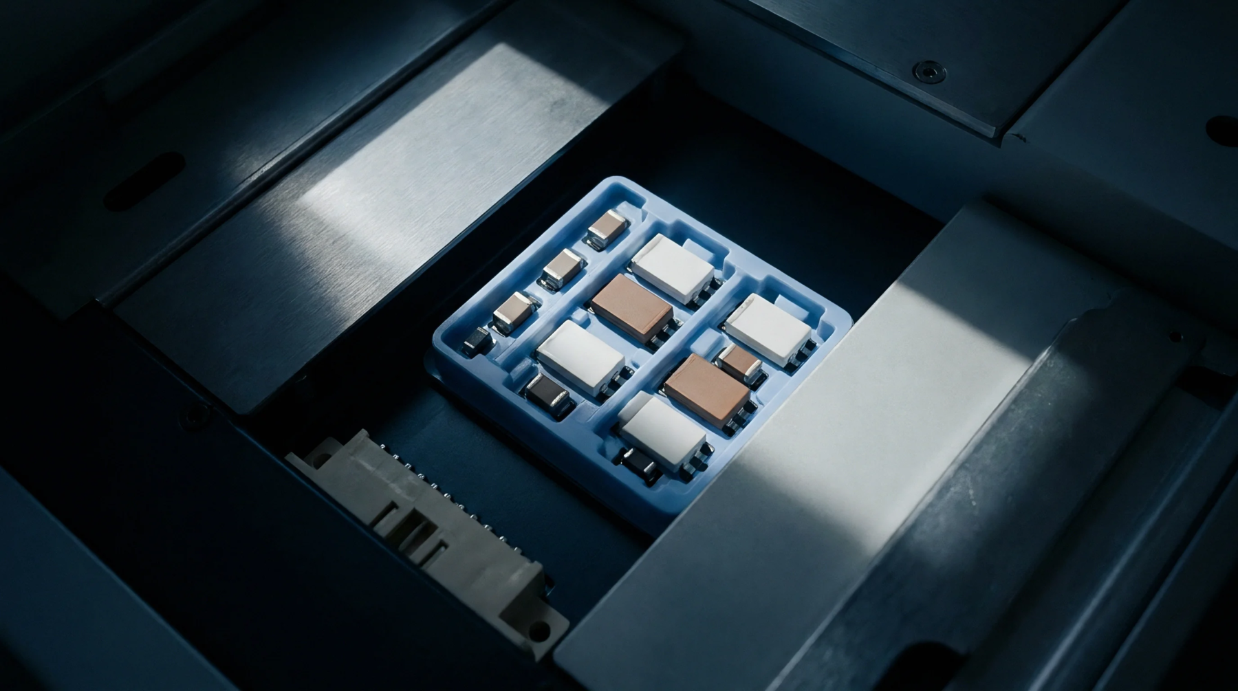
Optimizing solder paste rheology and stencil area ratios above 0.66 drives transfer efficiency stability and eliminates fine-pitch assembly defects.

Selecting dielectric substrates requires balancing dissipation factor, glass weave uniformity, foil roughness, and panel yields to meet high-speed impedance targets.
Layer registration drift budgets require RSS vector stacking of material shrink, tooling clearance, and drill wander to protect inner layer annular rings.

Volume PCB shops hold a real-world minimum annular ring of 0.002 inches for Class 2 designs when artwork grants 0.005 inches of nominal land margin over tool size.
Shear forces during vacuum pressing shift heavy copper traces when resin flow velocity exceeds interfacial bond strength, requiring optimized aspect ratios.
Unambiguous contract allocation caps assembly liability at process fees while tying thermal damage claims to independent coupon microsectioning evidence.
Non-Newtonian resin flow inside thin prepreg micro-channels governs void formation, trace displacement, and dielectric thickness stability during high-pressure lamination.

Mid-loss laminates paired with low-roughness copper foil match high-cost ultra-low-loss performance at a fraction of the raw panel price.
Specifying staggered microvias and single-press HDI stackups preserves multi-vendor competition while cutting panel scrap costs.

Multilayer PCB fabrication laminates etched copper cores and prepreg under heat and vacuum, creating vertical interconnects through precision drilling and copper electroplating.
Expertise is a utility, not a secret. sentiention™ publishes its working knowledge as open reference: intelligence layer covering the materials it sources, the markets it enters, and the reference that serves both.