Internal Shielding
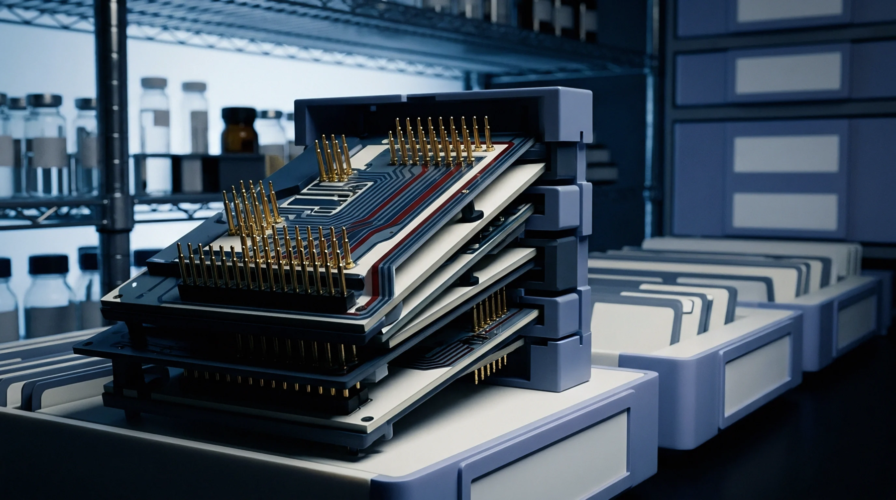
Continuous sheets of conductive material embedded within the substrate of a printed circuit board provide stable voltage references and reduce electromagnetic interference. These structures, configured as multi layer copper planes, distribute electrical power and ground returns across the entire surface area of the assembly. Their presence helps contain high-frequency radiation and establishes the characteristic impedance of adjacent trace layers.
By acting as reference pathing, the metal sheets minimize the loop area of signals, which decreases susceptibility to external electrical noise.
Signal Integrity
High-speed digital designs require a continuous path for return currents to prevent signal distortion. When multi layer copper planes are interrupted by gaps or holes, the return current must detour around the obstruction, which increases loop inductance and causes crosstalk. Engineers plan the stackup to ensure that every critical signal layer runs adjacent to an unbroken solid reference sheet.
This layout practice maintains the integrity of high-frequency transitions, ensuring that the finished circuit meets the necessary emissions standards.
Fabrication Parameter
Lamination of multiple copper layers requires careful balancing of the copper density across the central axis of the board to prevent warping during thermal processing. Fabricators use dummy copper pour on sparse layers to match the thickness of multi layer copper planes elsewhere in the stackup. During the etching process, acid baths remove unwanted metal, leaving only the designated plane structures and trace patterns.
If the board features large uninterrupted copper areas, thermal relief pads must be implemented around component pin connections to prevent solder from freezing during assembly. Without these thermal reliefs, the mass of the internal copper draws heat away too quickly from the pad during wave or manual soldering.