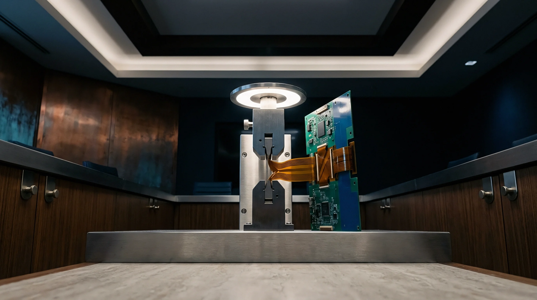
Test Interface
Custom printed circuit assemblies act as the physical bridge between automated test equipment test heads and packaged integrated devices during high-volume production testing. An ate load board routes high-speed signals, power supply rails, and control lines from pogo pin blocks on the test system to dedicated sockets. Controlled impedance traces and multi-layer power planes prevent signal degradation across millions of insertion cycles.
Board thickness often exceeds standard tolerances to prevent flexing under socket clamping forces.
Socket Degradation
Signal integrity deteriorates over extended usage due to mechanical fatigue and contact surface contamination. An ate load board exhibits trace wear, pogo pin pad pitting, and localized dielectric breakdown after prolonged exposure to high device socketing forces. Periodic planarity checks isolate surface warp before contact misalignment induces false yield losses.
Loadboard Acceptance
Automated optical inspection paired with automated time-domain reflectometry confirms trace continuity and impedance profiles prior to line deployment. Signal paths on an ate load board must maintain strict tolerance bounds for insertion loss and crosstalk to avoid corrupting silicon characterization metrics. Verification testing validates pin-to-pad resistance across all signal channels before the board enters active production support.
Signal path degradation outside specified parameters mandates planar re-sanded refurbishing or total assembly replacement.