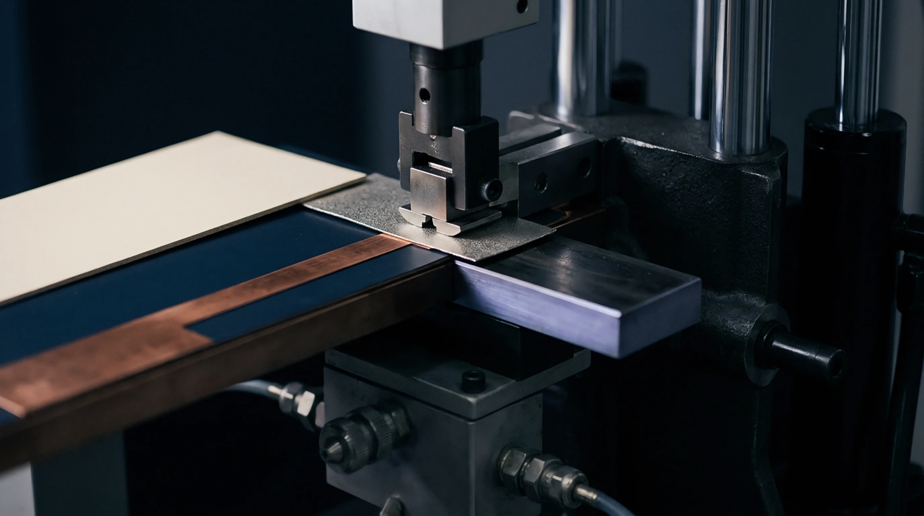
Surface Ratio
Traces of plated copper left across a given dielectric plane determine copper area density within printed circuit board fabrication. Manufacturers measure this percentage during inner layer imaging to verify that current carrying capacity matches thermal dissipation limits without bridging adjacent traces. Excess metal raises etching difficulty during chemical removal stages, whereas sparse coverage leaves circuits vulnerable to current crowding and localized heating failures.
Automated optical inspection equipment scans finished panels to calculate the ratio of metallic features to total board surface area. Etch factor calculations rely on this metric to adjust undercut compensation during subtractive processing of heavy copper weight designs.
Thermal Load
Dissipation performance depends directly on the spatial distribution of conductive pathways across multi layer assemblies. Power planes transfer heat away from high density component mounting zones toward external chassis interfaces. High metal coverage ratios restrict dielectric resin flow during lamination cycles, creating potential voids if press pressures remain unadjusted.
Engineers evaluate these structural distributions prior to layout release to prevent localized warping during reflow soldering thermal excursions.
Deposition Control
Plating baths require strict current density adjustments when panels feature widely varying trace concentrations across the working area. Insufficient metal deposition in dense zones triggers open circuit defects during subsequent etching steps, while overplating in sparse regions produces thick copper shoulders that degrade solder mask adhesion. Chemical replenishment rates adapt to the consumed metal volume calculated from the surface coverage data of each production lot.
Electroplating uniformity prevents localized resistance variations that could compromise signal integrity in high speed digital applications.