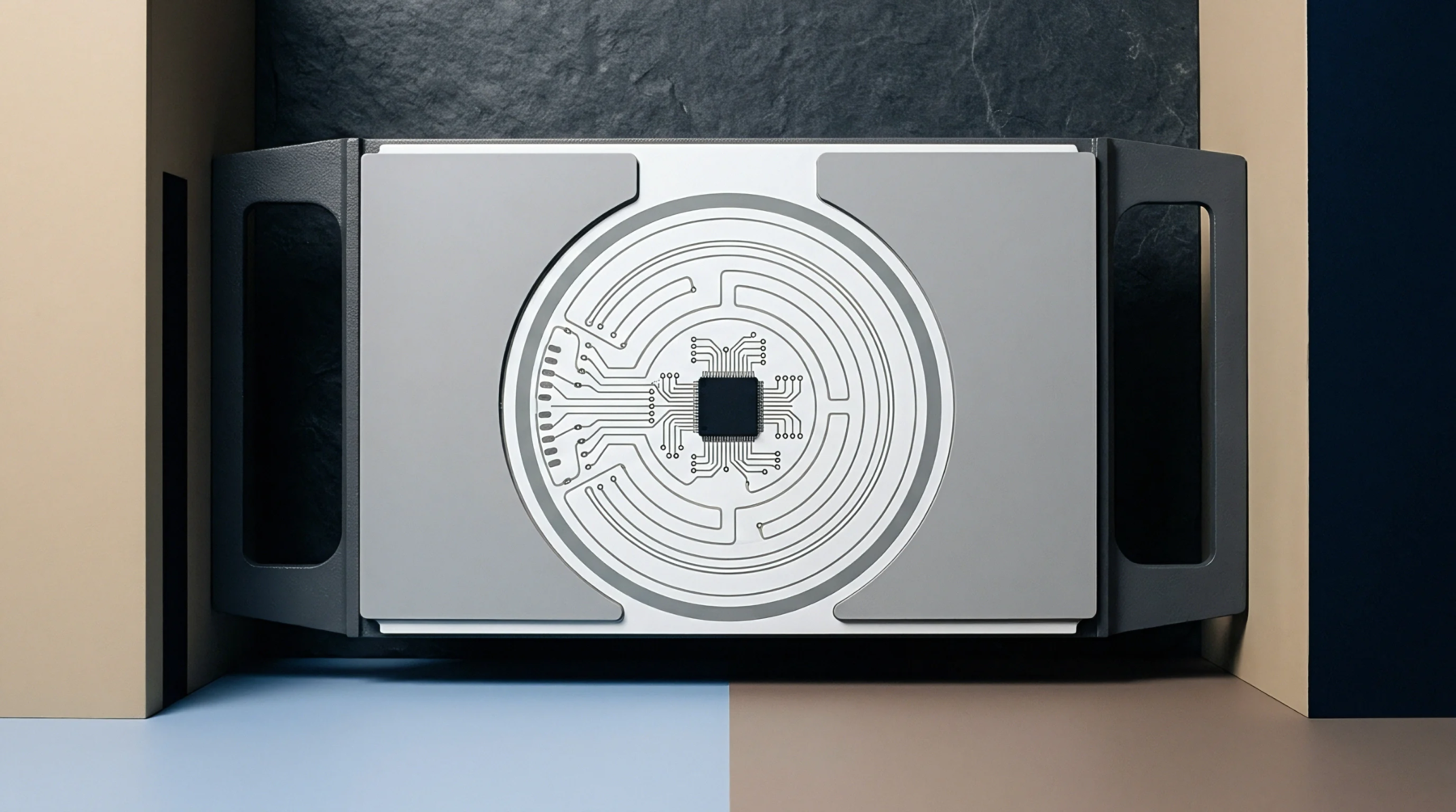
Electrical Transmission
Paired conductors transmit information through equal and opposite voltage swings relative to a common reference. Differential signaling relies on the receiver detecting the potential difference between two traces. This method provides immunity to electromagnetic interference because noise typically couples into both paths equally.
Fabricators control the impedance of these pairs by managing the trace width, spacing, dielectric thickness and copper weight.
Common Suppression
External noise sources affect both lines in the pair simultaneously and are canceled out at the receiving end of the circuit. Because the receiver subtracts one signal from the other, any voltage shift present on both conductors disappears during the calculation of the differential voltage. This property allows for lower voltage swings and higher data rates across the printed circuit board.
Successful implementation requires tight coupling between the traces to ensure that environmental interference remains identical on each path. Designers specify precise tolerances for the gap between the conductors to maintain the required differential impedance throughout the signal path. If the spacing varies, the magnetic and electric field interactions between the traces fluctuate and create impedance discontinuities.
Layout Constraint
Maintaining identical lengths for each conductor in the pair prevents time skew that would otherwise degrade the signal quality. If one trace is longer than its partner, the signals arrive at different times and the cancellation of noise becomes less effective. Designers use serpentine routing to match these lengths within narrow tolerances defined by the operating frequency.
Unmatched pairs cause a portion of the signal to convert into common mode energy, which radiates as electromagnetic interference and potentially violates regulatory standards.