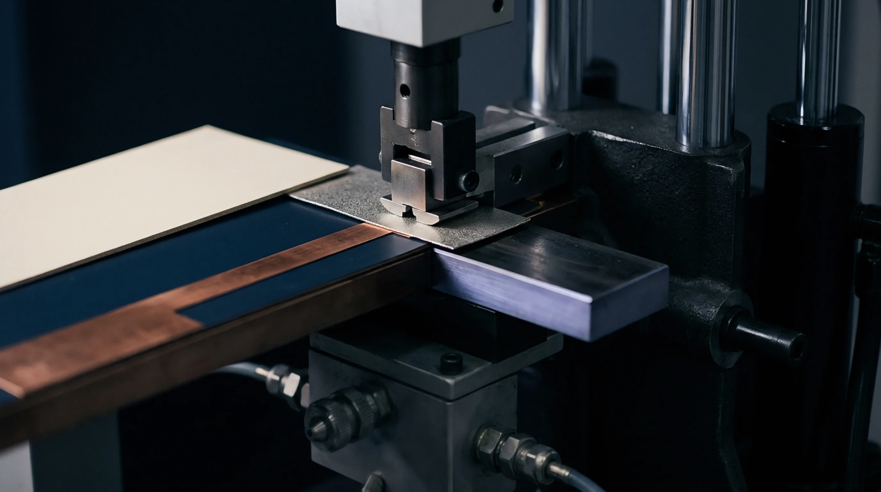
Geometric Compensation
Compensation algorithms adjust the laser photoplotter output to align with dimensional shifts in panel substrates. Direct imaging scaling modifies the coordinate data to correct for registration errors caused by thermal expansion or mechanical shrinkage in copper-clad laminates. These adjustments ensure that the circuit features land precisely on the copper pads during the subsequent pattern transfer process.
Process Logic
Data preparation software reads the measured deviation of the actual panel from the design intent before the exposure starts. Operators input these vectors into the imaging system to stretch or compress the light projection grid in both the X and Y axes. Each individual circuit layer receives a unique transformation coefficient based on the specific material movement observed in the press cycle.
Correcting these variances prevents open circuits or shorted paths at the assembly stage.
Correction Limit
Manufacturing tolerances dictate the boundary where software correction fails to salvage a misaligned panel. Excessive shrinkage shifts the features beyond the capability of the projection lens to maintain focus and resolution across the surface. This constraint forces the rejection of units that fall outside the elastic range of the photolithography process.
Proper management of these dimensional shifts remains the primary factor in high-density interconnect yield.