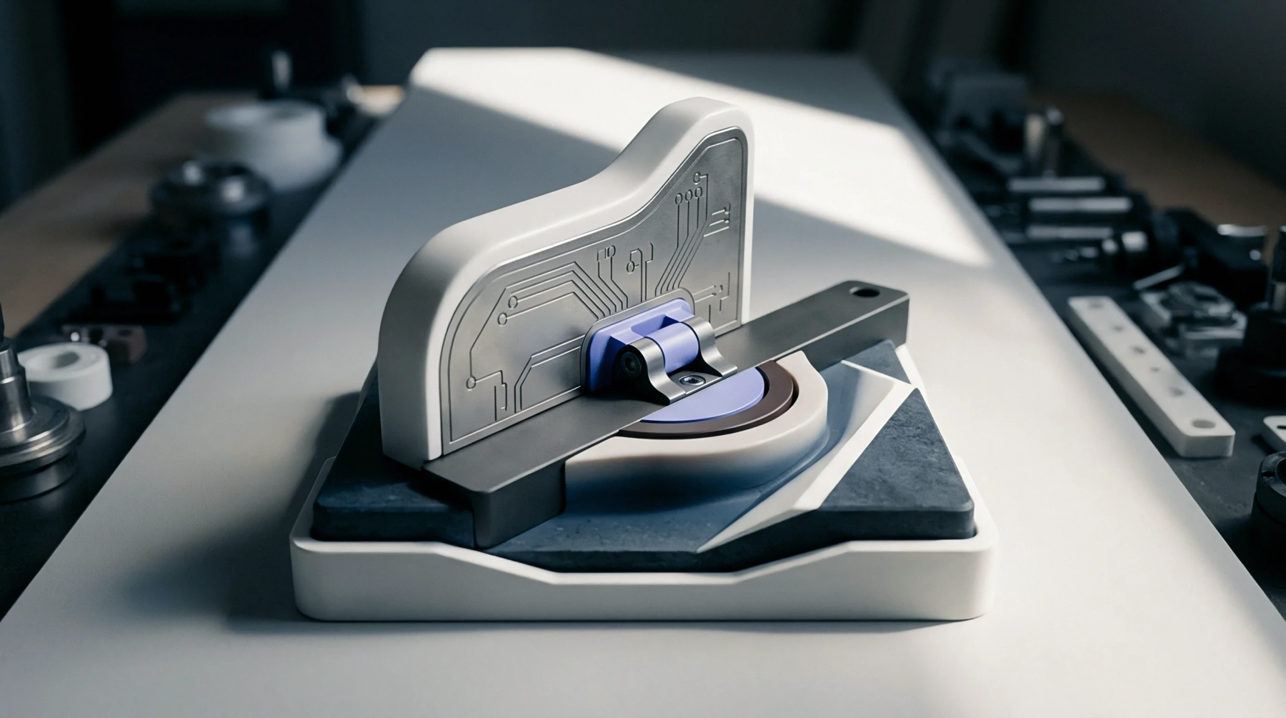
Surface Altitude Compensation
High-speed optical inspection systems must maintain fixed focus distances across substrate surfaces that exhibit local height variations. Focal plane tracking is the dynamic Z-axis positioning of an imaging lens or optical sensor assembly to follow variations in circuit board surface topology during scanning. It maintains sharp optical focus across warped substrates, uneven solder paste deposits, structural bow and variable component heights.
The process operates continuously during high-speed imaging moves and stops when image capture ends.
Inspection Resolution Stability
Substrate warpage and local board flexure alter the physical distance between inspection camera optics and the circuit board surface. Without dynamic focus adjustment, high-magnification lenses lose sharp focus, causing false defect reports or missed solder bridges. Focal plane tracking utilizes real-time laser displacement sensors to measure board surface altitude ahead of the optical path, driving high-speed Z-axis actuators to maintain perfect focus distance.
This active compensation preserves sub-micron spatial resolution across large, non-planar circuit panels without reducing scanning speed.
Optical Sensor Limit
Laser triangulation sensors measure surface height offsets at multi-kilohertz sampling rates to guide optical focus drives. Focal plane tracking operates within the vertical stroke range of the mechanical focus stage, beyond which optical defocus occurs.