Load Configuration
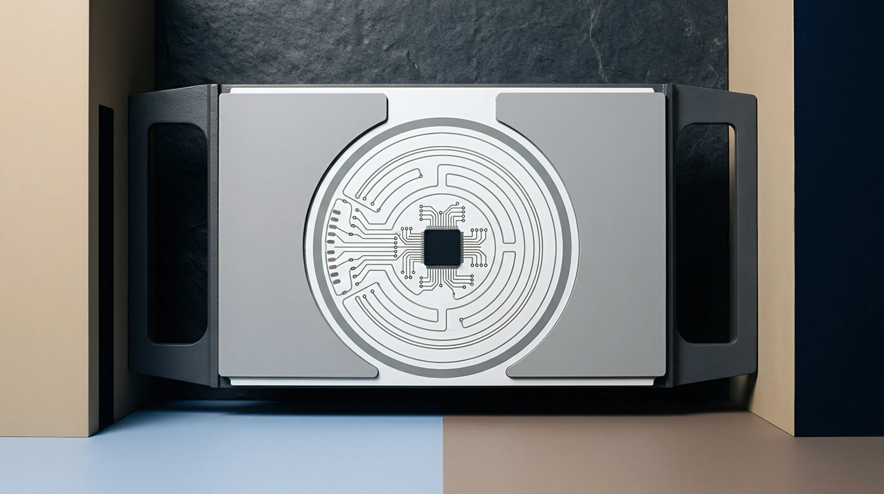
Mechanical evaluation of board assemblies employs a pair of upper loading noses and a pair of lower support anvils to apply a uniform bending moment. Executing a four-point bend test minimizes shear stresses between the inner spans while generating a region of constant bending strain. This specific load distribution ensures that components mounted in the center of the board experience uniform stress during testing.
Strain Zone Uniformity
Two distinct loading points on the upper surface create a symmetric stress field that avoids the sharp force spikes characteristic of three-point fixtures. This uniform distribution mimics the mechanical stresses that occur during assembly, panel de-panelization or housing integration. Substrate deformation is monitored using surface-mounted strain gages to correlate physical board curvature with mechanical loads.
Solder Fatigue Assessment
Electrical continuity monitoring during loading identifies the exact moment of solder ball fracture or pad cratering beneath ball grid array components. By applying repetitive cyclic loads, this setup determines the fatigue limit of different solder alloys under controlled deflection rates. Microscopic cross-sectioning after testing reveals whether the failure occurred within the bulk solder, the intermetallic compound layer, or the copper pad, helping designers optimize the pad geometry for improved board durability.
This failure analysis is instrumental in validating assembly processes before initiating high-volume manufacturing.