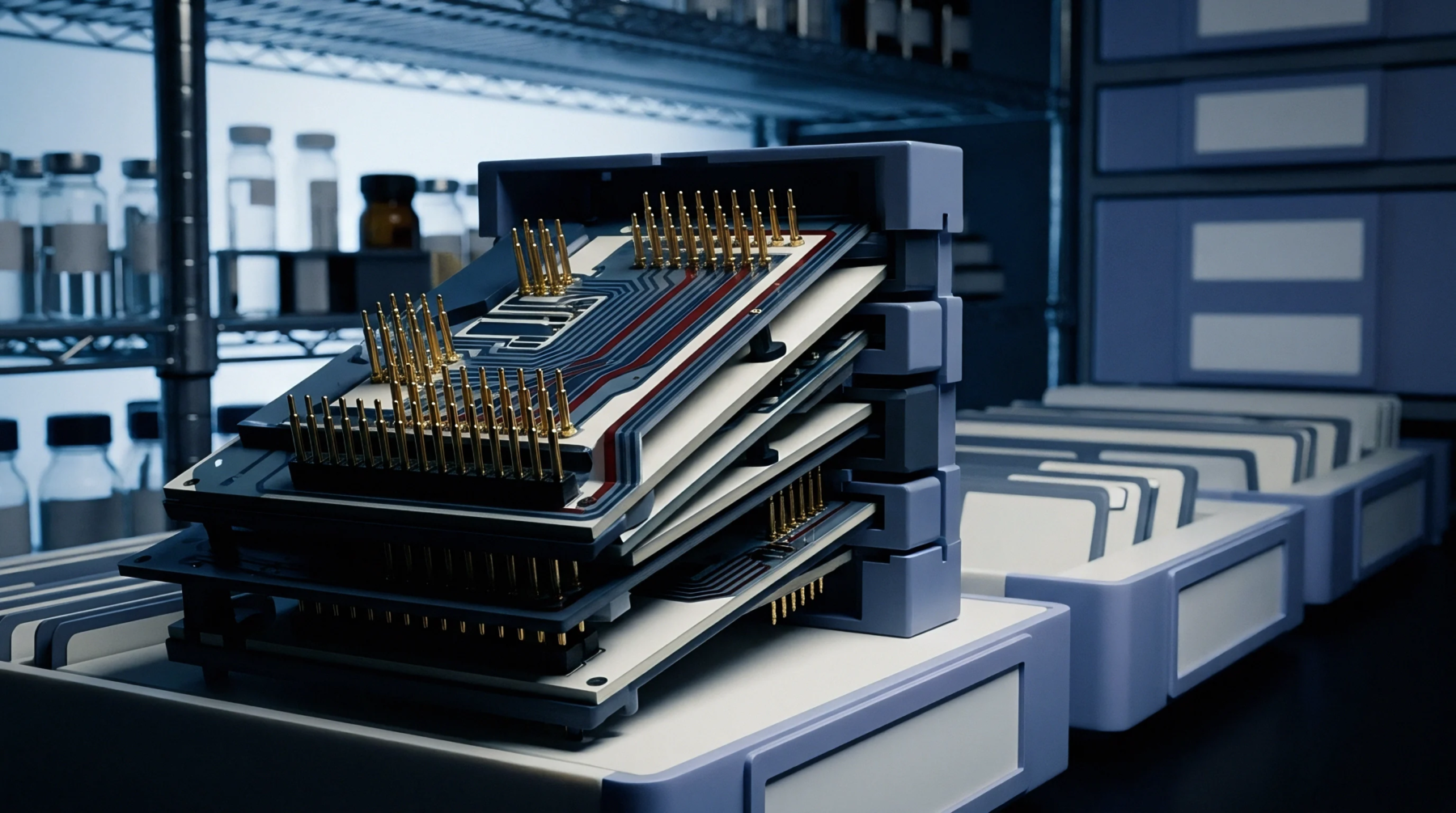
Magnetic Coupling
Geometric configurations of conductive paths define the total magnetic flux surrounding a current carrying circuit by enclosing the area between the supply and return traces. Circuit designers manage loop inductance by minimizing the physical space between these paths to ensure signal integrity and reduce electromagnetic emissions. Larger areas increase the magnetic field concentration per unit of current, which generates higher levels of parasitic noise.
Lower values restrict the generation of unwanted signals during high speed switching events. Ground planes placed directly beneath signal layers reduce the area available for flux lines. This reduction lowers the reactance that opposes rapid changes in current flow.
Effective layout strategies prioritize the proximity of return currents to suppress these adverse magnetic interactions.
Fabrication Geometry
Boards rely on the precise registration of copper layers to maintain intended trace separation across complex multilayer stacks. Variations in prepreg thickness change the distance between signal conductors and reference planes. Such deviations alter the area enclosed by the current path during manufacturing.
Engineers verify these properties through impedance testing on coupons placed along the panel edge. Precise dielectric control limits the divergence of current return paths from the primary trace. Small gaps between these conductors keep the parasitic energy storage within defined operational tolerances.
Manufacturers adjust etching processes to ensure trace profiles allow for consistent current distribution. Consistent thickness across the board prevents localized areas of high magnetic coupling. Careful alignment of layers during lamination secures the stability of the entire network.
Assembly Coupling
Reflow soldering processes determine the final orientation of components that connect to these conductive loops. Deviations in solder volume create unexpected parasitic bridges that enlarge the total circuit area. Automated optical inspection identifies excessive material that disrupts the design intent.
Proper pad design restricts the flow of solder and prevents the expansion of the electrical loop during heating. Components located too far from their decoupling capacitors increase the path length and heighten susceptibility to noise. High frequency performance demands short paths to ensure the loop inductance remains below levels that trigger unintended oscillations.
Stable mechanical connections ensure the integrity of these paths under thermal stress. Lowering these physical lengths creates a more stable electromagnetic environment.