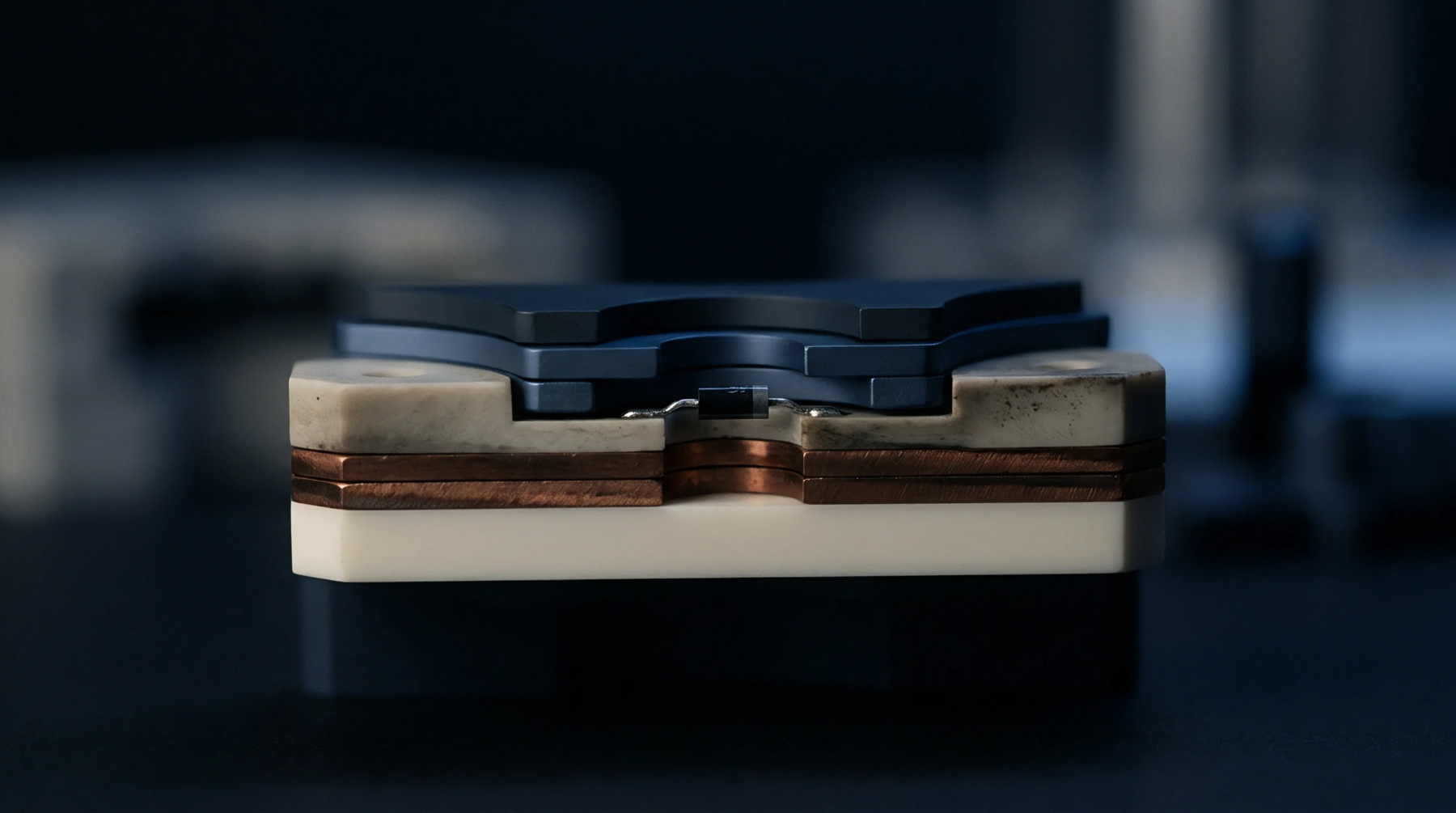
Thermal Threshold
Cumulative heat exposure constraints restrict the number of desoldering, component removal and site re-soldering cycles permitted on a single printed circuit board location during manufacturing touch-up. Standard rework limits protect copper foil adhesion, internal barrel plated through-holes and adjacent solder joints from thermal and mechanical degradation induced by localized hot air or soldering irons. Industry standards establish that individual component locations must not undergo more than two to three thermal rework cycles without formal engineering approval.
The boundary of this rule governs post-assembly repair and component replacement operations, terminating once the entire circuit assembly is scrapped or accepted for final potting and conformal coating.
Degradation Mechanism
Localized application of rework heat induces localized thermal expansion stresses that exceed standard reflow oven profiles. Repeated heating cycles with hot-air nozzles or manual soldering tips accelerate intermetallic compound growth at the copper-to-solder interface, transforming ductile solder joints into brittle intermetallic layers prone to mechanical shock fracture. Excessive thermal dwell times degrade the glass transition temperature of the epoxy resin beneath the solder pad, weakening adhesive bonds between copper foils and dielectric laminate.
Weakened adhesive strength causes pad lifting, trace delamination and internal barrel cracking in adjacent plated through-holes. Nearby passive components can undergo secondary reflow, forming disturbed solder connections or micro-bridging beneath low-clearance component packages.
Process Verification
Controlled rework protocols require calibrated temperature-controlled soldering stations, automated component placement alignment optics and programmable hot-air reflow tools. IPC-7711/7721 repair standards define acceptable workmanship criteria and allowable tool temperatures for trace repair, pad replacement and component desoldering. Quality assurance tracking logs record every touch-up action by component designator and serial number to enforce maximum allowable thermal cycle rules.
Exceeding established limits mandates non-destructive micro-focus X-ray inspection and destructive microsection testing on lot samples to verify that internal circuit layers remain structurally intact. Traceable repair documentation confirms compliance with commercial contract specifications before finished boards ship to customers.