Deflection Tolerance
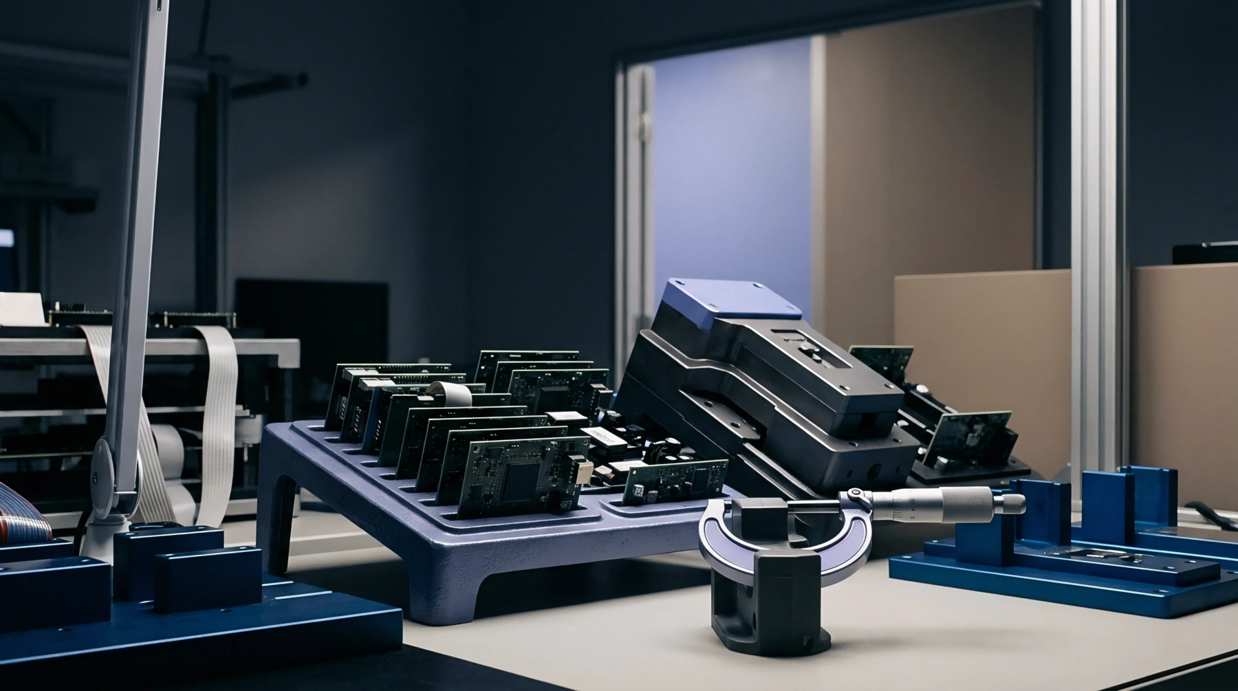
Mechanical strain limits dictate the maximum degree of curvature permitted for a populated printed circuit assembly during manufacturing, handling, and testing sequences. This substrate bending limit prevents copper trace fracturing and solder joint detachment that occur when rigid board materials experience excessive mechanical tension. Material thickness, laminate composition, and the density of surface mount components define the threshold where damage begins to occur.
Mechanical Stress
Excessive curvature generates tensile forces across the board surface, creating stress concentrations at the base of heavy or stiff components. Solder joints experience shear forces when the assembly shifts beyond the elastic range of the laminate. Controlled fixtures limit this movement during board separation from panels, in-circuit testing, and final housing insertion.
Small component packages often tolerate higher strain rates than larger connectors or ceramic capacitors. The risk of internal delamination between fiberglass layers increases when the displacement exceeds the specified curvature coefficient.
Assembly Compliance
Fabrication standards categorize boards by their ability to withstand bending without incurring permanent structural failure or functional disruption. Process engineers establish support pin locations and fixture distances to keep board flexure beneath the critical point during high pressure testing cycles. Strain gauge verification provides data to validate these geometric constraints against the material properties of the laminate.
Rigid hardware secures the circuit during installation to ensure the design remains within the established safety margin.