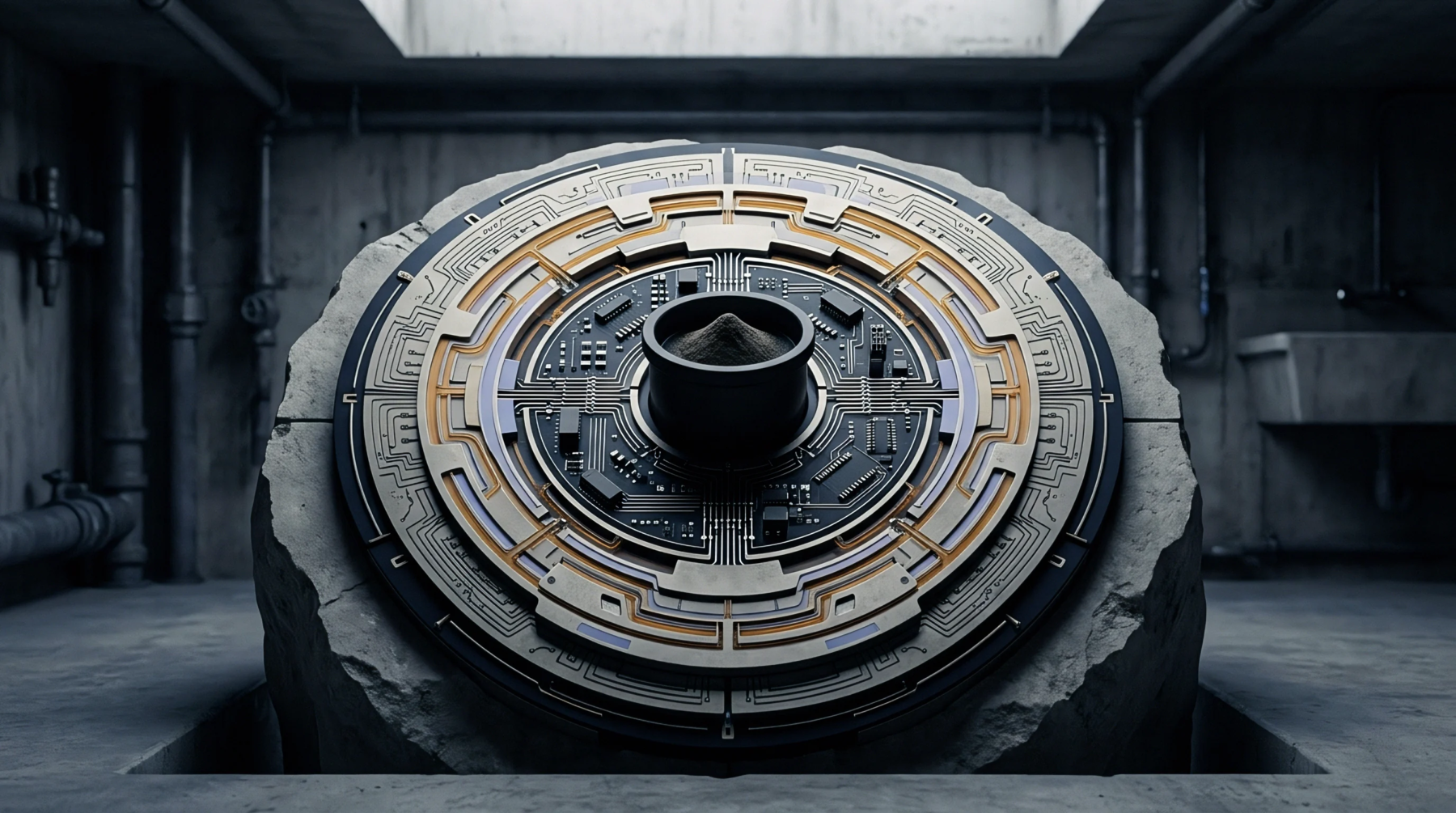
Alignment Precision
Positional accuracy of the interface pins relative to the circuit board pads determines the reliability of automated electrical testing. Proper test fixture registration ensures that every probe makes contact with its intended target without drifting onto the solder mask or adjacent components. Component alignment depends on the mechanical tolerances of the fixture plate, guide pins, board fabrication and assembly alignment.
A failure in registration results in false rejects, where functional boards appear defective because the probes cannot establish a circuit.
Mechanical Guide
Tooling holes in the board act as the primary reference for the fixture pins. These holes must be drilled with high precision to match the layout of the test probes. During the test cycle, the board is pressed down onto these pins, which fix its position in the X and Y axes.
Wear on the tooling pins or enlargement of the board holes can degrade the accuracy over time.
Tolerance Accumulation
Total error in the probe position comes from a combination of several independent factors. The fabrication of the fixture involves drilling thousands of small holes, each with its own minor deviation from the ideal coordinate. Thermal expansion of the fixture material and the board can shift the position of test fixture registration targets.
To manage these errors, engineers use floating probes or larger test pads to provide a wider margin for error. System accuracy remains reliable through regular calibration and inspection of the fixture.