Fabrication Geometry
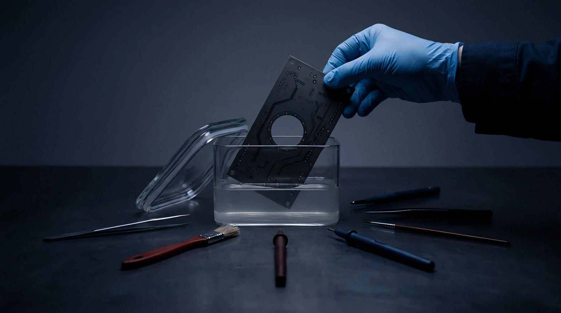
Chemical etching processes remove copper from laminated substrates through controlled exposure to corrosive solutions. The trapezoidal etch factor quantifies the ratio between the depth of the removed material and the width of the lateral undercut occurring beneath the photoresist edge. Manufacturers calculate this value by measuring the difference between the base width and the top width of the trace profile after the completion of the etching cycle.
Precise control over this geometric deviation prevents signal integrity degradation caused by unexpected impedance shifts along high-speed transmission lines.
Calculation Methodology
Analysts determine the result by dividing the vertical depth of the etched sidewall by the horizontal width of the undercut on one side of the conductor. High values denote a nearly vertical wall profile, whereas low values indicate significant lateral erosion that rounds or narrows the trace geometry. Engineers use cross-sectional inspection of coupons to verify that these values remain within the tolerances defined by the board design requirements.
Operational Consequence
Consistent etch profiles guarantee reliable performance during the subsequent assembly stage where solder masks and conformal coatings must adhere to uniform copper surfaces. Deviations from expected profiles lead to uneven skin effect losses or mismatched impedance values in fine-pitch circuit designs. Proper management of this physical characteristic improves the predictability of board-level interconnects across production cycles.