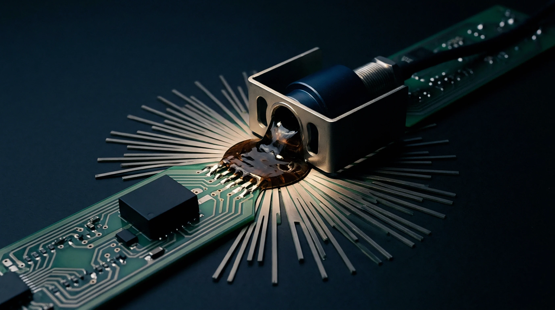
Force Unbalance
Mechanical pressure variations across a testing interface occur when contact density is unevenly distributed relative to the board supports. In scenarios involving asymmetrical probe loading, the downward force of pogo pins creates a moment arm that acts on the unsupported regions of the laminate. This effect generates concentrated stress near the hinge or corner of the test fixture.
Stress Distribution
Contact forces on a single probe tip range from fifty to one hundred grams depending on spring tension. When these forces aggregate on one side of a large array, the imbalance produces significant substrate curvature. Engineers calculate the resultant vector to ensure it does not exceed the local bending limit of the dielectric or the strain limit of the nearest solder joint.
If the force center shifts away from the structural supports, the panel may bow during the downward stroke of the press. This curvature introduces the risk of pad lifting or surface finish micro-cracks in brittle intermetallic layers. Advanced simulation tools model these loads during the design phase of the bed of nails to prevent localized deformation.
Deflection Countermeasure
Strategically placed push fingers counteract the vector of the probe array. These fingers translate the pressure from the top plate directly into the underlying support plate.