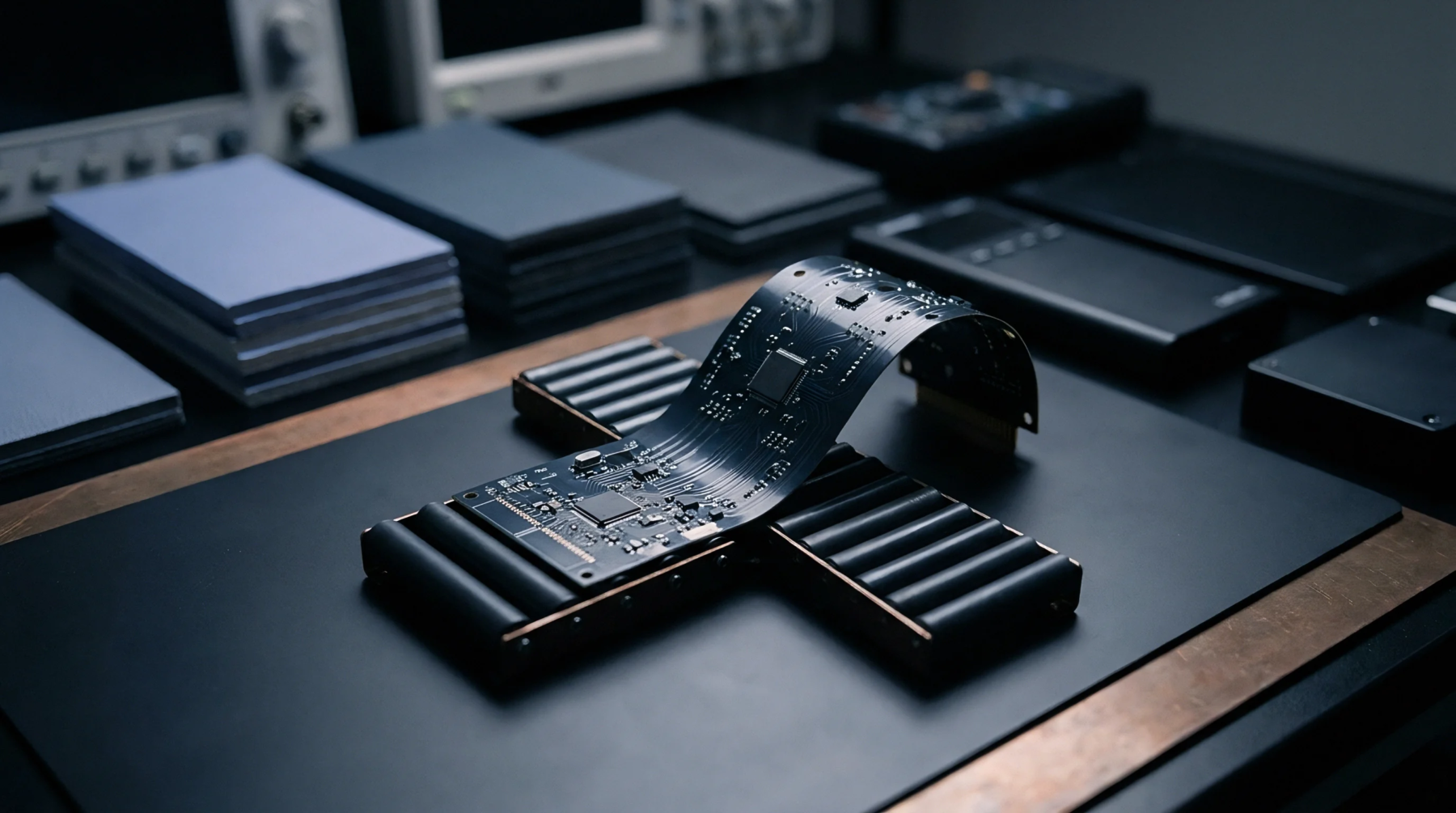
Reference Standard
Automated inspection and testing systems use a verified, defect-free circuit board to establish a baseline for subsequent production runs. The golden board calibration process loads this known-good reference into automated optical inspection or flying probe testers to align sensor thresholds and test limits. This step prevents false calls and ensures consistent defect detection across different shifts.
Machine Alignment
Optical cameras on the inspection system scan the fiducial markers and copper features of the reference board to map coordinate matrices. The system registers these features against the Gerber design data to establish the nominal positions of all components and traces. Any variance in lighting, camera angle, or focus is compensated for during this calibration, ensuring that subsequent boards are measured against a stable baseline.
This activity is particularly important when dealing with matte black or high-reflection solder masks, which confuse automated vision algorithms if the illumination intensity is not properly adjusted.
Verification Interval
Quality procedures require this routine at the start of each production lot or after any software modifications. By comparing current scan results to the saved digital signature of the golden board, operators can detect drift in the machine’s vision or mechanical systems. This discipline maintains high-capacity throughput without risking the escape of critical assembly defects.