Moisture Sensitivity Level Classification and Component Storage Standard
MSL classification defines component floor life to prevent internal steam popcorning during reflow through controlled barrier packaging and dry baking.


Rating
A package entering a convection reflow zone at 245 degrees Celsius turns trapped liquid into steam in four seconds. Moisture Sensitivity Level classification establishes where plastic encapsulated microcircuits absorb enough ambient humidity to risk destruction during surface mount thermal cycles. Under IPC/JEDEC J-STD-020, non-hermetic solid-state surface mount devices fall into eight distinct tiers.
These levels set a component’s allowed floor life after removal from hermetic packaging under factory conditions ~ defined as 30 degrees Celsius and 85 percent relative humidity for Level 1, or 30 degrees Celsius and 60 percent relative humidity for Levels 2 through 6.
Qualification starts with electrical testing, optical inspection, and baseline acoustic microscopy to map pre-existing internal voids or interfacial separations. Test parts then enter moisture soaking chambers calibrated to accelerate water absorption before undergoing three consecutive simulated reflow passes. Peak package body temperatures during qualification range from 215 degrees Celsius to 260 degrees Celsius depending on volume and thickness; thinner packages carry higher peak ratings because their lower thermal mass heats faster across the reflow belt.
| Level | Floor Life Window | Standard Soak Conditions | Accelerated Soak Conditions |
|---|---|---|---|
| MSL 1 | Unlimited at 30 C and 85 percent RH | 168 hours at 85 C and 85 percent RH | Not applicable |
| MSL 2 | 1 year at 30 C and 60 percent RH | 168 hours at 85 C and 60 percent RH | Not applicable |
| MSL 2a | 4 weeks at 30 C and 60 percent RH | 696 hours at 30 C and 60 percent RH | 120 hours at 60 C and 60 percent RH |
| MSL 3 | 168 hours at 30 C and 60 percent RH | 192 hours at 30 C and 60 percent RH | 40 hours at 60 C and 60 percent RH |
| MSL 4 | 72 hours at 30 C and 60 percent RH | 96 hours at 30 C and 60 percent RH | 20 hours at 60 C and 60 percent RH |
| MSL 5 | 48 hours at 30 C and 60 percent RH | 72 hours at 30 C and 60 percent RH | 15 hours at 60 C and 60 percent RH |
| MSL 5a | 24 hours at 30 C and 60 percent RH | 48 hours at 30 C and 60 percent RH | 10 hours at 60 C and 60 percent RH |
| MSL 6 | Mandatory bake before use | Time on label at 30 C and 60 percent RH | Not applicable |
Package thickness drives the thermal gradient from the outer mold compound to the internal die paddle. A 1.0 millimeter thin quad flat pack reaches peak core temperature forty seconds ahead of a 3.5 millimeter ball grid array. The specification bins device geometry into thickness bands ~ below 1.6 millimeters, 1.6 to 2.5 millimeters, and 2.5 millimeters or greater ~ against package volumes under 350 cubic millimeters, 350 to 2000 cubic millimeters, and over 2000 cubic millimeters.
Process engineers set profile limits where these parameters intersect. Profiles exceeding the assigned classification temperature by even two degrees accelerate mold compound glass transition degradation.
Peak package temperature ratings fall from 260 degrees Celsius to 245 degrees Celsius when package volume expands past 2000 cubic millimeters under lead-free reflow.
Scanning acoustic microscopy checks structural integrity after three thermal passes, pulsing high-frequency ultrasound between 15 megahertz and 230 megahertz through deionized water to read internal material interfaces. Delamination between the epoxy molding compound and the silicon die face reflects high-amplitude phase-inverted energy. J-STD-020 sets clear failure thresholds: any delamination across the active die surface, any crack traversing external resin surfaces, or delamination covering more than twenty percent of the leadframe paddle interface prompts immediate lot rejection.
Under Section 6.2.1 of IPC/JEDEC J-STD-020, changing the mold compound formulation, leadframe plating, or die attach chemistry invalidates existing qualification, requiring full moisture soaking and acoustic evaluations across three independent assembly lots.

Steam
Epoxy mold compounds absorb atmospheric moisture through microscopic capillary pathways in the polymer network. Absorbed water sits inside the cured resin as both unbound free molecules and hydrogen-bonded clusters. Saturated mold compound holds up to 0.5 percent water by weight under factory exposure.
Reflow heating vaporizes this trapped moisture almost instantaneously.

Why Do Thin Quad Flat Packages Crack Faster?
Rapid thermal transitions generate steep internal pressure gradients as convection ovens ramp assemblies at 1.5 to 3.0 degrees Celsius per second toward peak liquidus temperatures. Trapped liquid moisture expands sixteen hundred times in volume upon phase transition, governed by Clausius-Clapeyron thermodynamics. Vapor pressure inside internal voids exceeds 4.0 megapascals once package temperature passes 220 degrees Celsius.
Thin packages simply lack the resin cross-section needed to resist this internal pneumatic force.
Resin mechanical strength drops sharply at the same time. Mold compounds hit their glass transition point between 120 and 160 degrees Celsius, where elastic modulus falls by eighty percent. By 250 degrees Celsius, the mold compound behaves like soft rubber while internal steam reaches explosive pressures.
This confluence shears the adhesive bond holding resin to copper leadframes and gold or copper bond wires.
Solder reflow temperatures reduce molding compound tensile strength by four fifths while internal steam pressure climbs past forty atmospheres.
Popcorning represents the extreme outcome of this pressure release. Expanding steam forces the mold compound away from the silicon die surface or central metal paddle, forming a domed acoustic void. Pressure accumulates until the epoxy cracks outward toward the package exterior.
A sharp acoustic report often accompanies the rupture on the reflow belt, snapping internal bond wires or fracturing the silicon die across active circuit nodes.
Microcracks create subtle but catastrophic failure risks. Steam can vent through narrow fissures extending from the leadframe edge toward external package pin roots without splitting the outer housing entirely. Atmospheric flux residues, cleaning solvents, and ionic contaminants infiltrate these fissures during post-reflow handling, driving dendritic copper growth that bridges adjacent conductors under applied field bias.
- Interfacial delamination severs thermal dissipation paths between the silicon substrate and the ground paddle, driving junction temperatures beyond operating safety margins.
- Bond wire necking stretches intermediate gold and copper loops upward during mold displacement, creating intermittent open circuits that escape initial automated electrical test benches.
- Silicon die fractures originate from localized stress concentration points along leadframe edges, slicing through upper passivation layers and cutting internal signal traces.
- Cratered die attach leaves mechanical voids under large power amplifier transistors, provoking immediate localized thermal runaway upon primary power application.
- External resin blistering deforms component planar seatings, lifting neighboring perimeter leads off solder paste deposits and causing open solder joints.
Differential thermal expansion compounds the steam mechanism. Copper leadframes expand at seventeen parts per million per degree Celsius, silicon at three, and mold compound at twelve below its glass transition point ~ jumping to fifty above it. Moisture acts as a plasticizer, lowering the glass transition temperature by as much as twenty degrees Celsius and pushing saturated packages into rubbery expansion much earlier in the oven cycle.
The resulting shear stresses tear internal package interfaces apart before solder paste achieves liquidus.
Overlooking moisture saturation causes internal silicon fracture, interfacial delamination, latent field failures, and costly whole-board production scrapping.

Vault
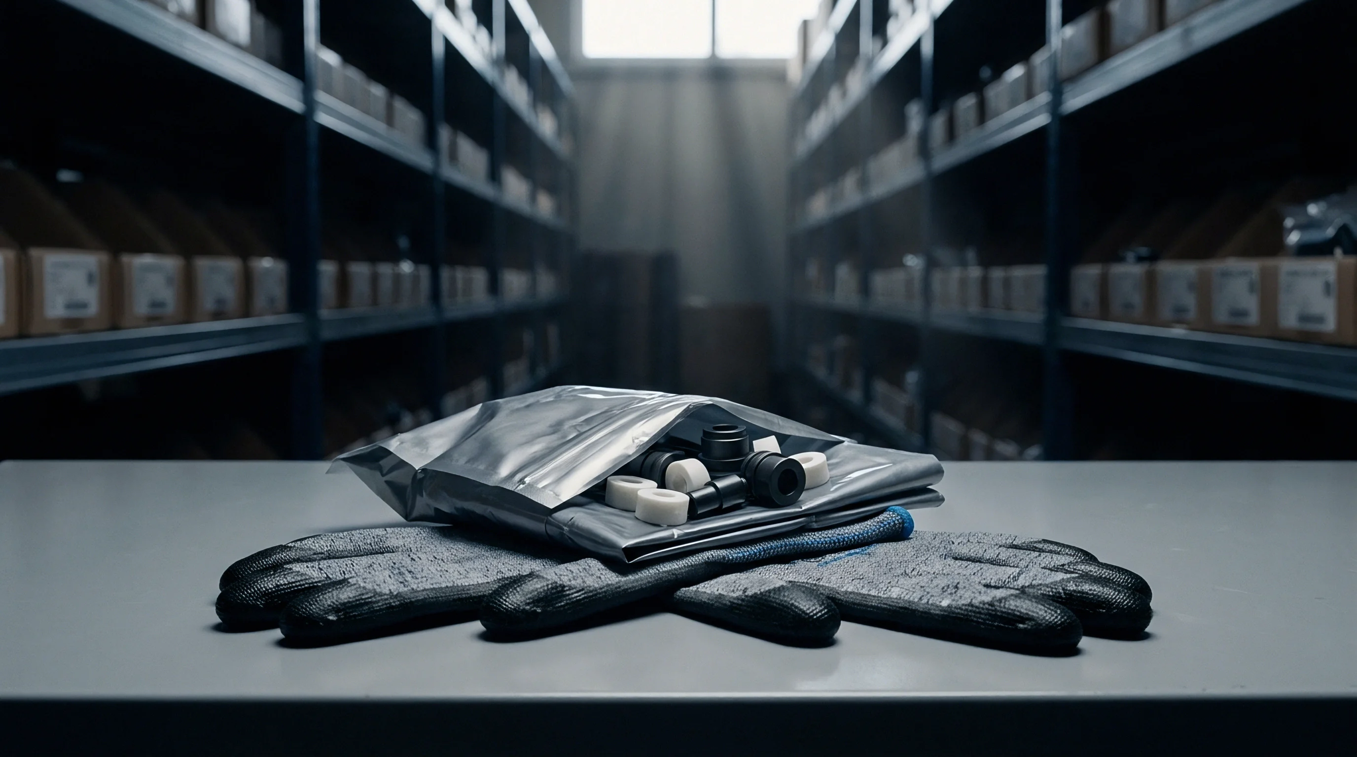
Protecting moisture-sensitive surface mount devices demands dry packaging systems that block atmospheric vapor penetration. IPC/JEDEC J-STD-033 governs the methods, materials, and processes used to pack, ship, and handle these parts. Standard dry packaging relies on three physical tools: a Moisture Barrier Bag, calculated quantities of desiccant clay or silica gel, and a calibrated Humidity Indicator Card.
Moisture Barrier Bags use multi-layer laminated films with aluminum foil or metallized polyester sheets sandwiched between protective polyamide and heat-sealable polyethylene layers. Under ASTM F1249 test parameters at 40 degrees Celsius and 90 percent relative humidity, compliant bags maintain a Water Vapor Transmission Rate below 0.002 grams per 100 square inches over twenty-four hours. Physical puncture resistance exceeds twenty-five pounds under FTMS 101C Method 2065, and clean heat seals are applied at 150 to 200 degrees Celsius across a ten-millimeter boundary band to prevent perimeter pinhole leaks.
- Inspect barrier pouches for external punctures, creases, or split vacuum seals prior to loading reels into automated feeder carts.
- Examine the indicator card immediately upon opening the foil pouch to verify the spot array retains its active blue color state.
- Log component floor clocks within the factory enterprise software system, recording part number, lot code, package thickness, and unseal timestamp.
- Transfer exposed tape directly into nitrogen-purged desiccator storage cabinets whenever assembly changeovers exceed two hours of idle feeder dwell.
- Seal depleted reels inside fresh moisture barrier pouches with newly calculated desiccant units before returning partial carrier tapes to warehouse racks.
Desiccant sizing follows exact mathematical formulas defined in J-STD-033, calculated from bag surface area, target interior humidity, and carrier media mass. At 25 degrees Celsius, desiccant units absorb a minimum of 2.85 grams of water vapor at 20 percent relative humidity and 5.70 grams at 50 percent relative humidity. Plastic carrier trays and paper tape-and-reel materials introduce significant moisture mass into the sealed pouch.
| Packaging Media Variable | Calculation Formula per J-STD-033 | Key Physical Assumptions |
|---|---|---|
| Barrier Bag Area Term | U equals 0.038 multiplied by Bag Area in square inches | Assumes 12-month shelf life and WVTR of 0.002 g per 100 sq inches |
| Plastic Trays Included | Add 0.016 Units per gram of tray mass | Accounts for baked plastic tray moisture absorption capacity |
| Cardboard and Paper Reels | Add 0.032 Units per gram of cellulosic mass | Compensates for high equilibrium moisture holding in paper tape |
| Desiccant Rounding Rule | Round total computed Units upward to next whole integer | Prevents desiccant saturation before standard shelf expiry |
Dry storage cabinets provide line-side floor life extensions without requiring destructive heat cycles. Modern dry boxes maintain relative humidity levels below five percent using closed-loop desiccant rotor regeneration or continuous high-purity nitrogen purge. Parts classified as MSL 2 through MSL 5a placed within an atmosphere sustained below five percent relative humidity gain unlimited floor life storage, as low internal vapor pressure extracts surface moisture slowly without thermal stress.
Unbroken hermetic seals maintain dry pack component integrity across twelve full calendar months from the packaging date stamped on the barrier label.
Humidity Indicator Cards monitor internal package performance without electronic sensors. A standard card carries three chemically impregnated spots indicating relative humidity thresholds of five percent, ten percent, and sixty percent using cobalt chloride or alternative halide salts. Color transitions from blue to pink mark rising moisture ingress.
When the ten percent spot turns pink on an MSL 3 component, the package has absorbed critical moisture and requires thermal remediation before assembly reflow.
Unopened barrier bags can lose protective integrity during storage warehouse temperature spikes or after bag label dates expire.


Restoration
Thermal baking restores expired components by driving absorbed water molecules back across the mold compound boundaries. Process engineers apply specific temperature and duration matrix tables established in J-STD-033. Selection of baking conditions hinges on package thickness, established moisture sensitivity level, and the physical temperature endurance of the packaging carrier material.

Will Baking Restore Indefinite Floor Life?
Components removed from tape and placed into high-temperature metal trays endure 125 degrees Celsius bake cycles safely, expediting water desorption kinetics. An MSL 3 package thinner than 1.4 millimeters requires nine hours at 125 degrees Celsius to reset its floor life counter, whereas baking that same component at 40 degrees Celsius requires thirteen days inside a desiccated cabinet. High heat agitates molecular bonds, increasing diffusion rates outward through the epoxy matrix.
Carrier media constraints frequently prevent high-temperature cycles. Standard embossed plastic carrier tapes, cover films, and blue pickup tapes soften and melt at temperatures above 45 degrees Celsius. Low-temperature baking at 40 degrees Celsius and less than five percent relative humidity preserves tape integrity, avoiding manual de-taping and re-taping labor.
However, extended low-temperature bakes introduce secondary risks by holding parts at warm ambient states for several weeks.
| Package Thickness | Sensitivity Tier | Bake at 125 C (High Temp Trays) | Bake at 40 C and RH below 5 percent |
|---|---|---|---|
| Below or equal to 1.4 mm | MSL 2 | 5 hours | 7 days |
| Below or equal to 1.4 mm | MSL 3 | 9 hours | 13 days |
| Below or equal to 1.4 mm | MSL 4 | 11 hours | 15 days |
| 1.4 mm to 2.0 mm | MSL 3 | 18 hours | 24 days |
| 1.4 mm to 2.0 mm | MSL 4 | 21 hours | 27 days |
| 2.0 mm to 4.5 mm | MSL 3 | 27 hours | 37 days |
| 2.0 mm to 4.5 mm | MSL 5a | 48 hours | 68 days |
Baking exacts a distinct metallurgical penalty on component termination finishes. Lead-free solder terminations utilize matte tin, nickel-palladium-gold, or tin-silver-copper coatings over base copper leadframes. Thermal exposure accelerates intermetallic compound growth at the boundary interface.
Solid-state diffusion produces brittle copper-tin intermetallics, specifically Cu6Sn5 and Cu3Sn phases, which consume the solderable pure tin finish from the inside out.
Intermetallic growth rates double for every ten-degree rise in continuous thermal exposure. Extended baking generates excessive intermetallic thickness exceeding 1.5 micrometers, leaving inadequate free tin on the lead exterior. Solder paste flux cannot reduce oxidized intermetallics during convection reflow.
Wetting angles degrade from clean twenty-degree menisci to non-wetting conditions exceeding ninety degrees, provoking weak solder joints and solder balling defects.
Atmospheric oxygen oxidizes exterior lead finishes during unpurged oven bakes. Pure tin converts into stannous and stannic oxides, producing dull yellow terminal discolorations. Modern reflow lines require aggressive flux chemistry to break through heavy oxide skins.
Nitrogen-purged baking ovens limit terminal oxidation by reducing ambient oxygen concentrations below fifty parts per million during prolonged heat cycles.
Component manufacturers cap cumulative thermal baking exposure, typically permitting a maximum total bake time of ninety-six hours at 125 degrees Celsius across the operating lifespan of a component. Exceeding this boundary embrittles internal bond wire interfaces and causes internal mold compound shrinkage. Parts that exceed ninety-six hours of total thermal restoration face mandatory scrappage.
Bake components only when the moisture clock has truly expired, because unnecessary heat steals solderability from terminations long before it warps the resin body.

Intake
Receiving inspection serves as the primary barrier against wet components entering active production. Verification ensures incoming shipments match purchase specifications before goods enter surface mount staging areas. Damaged foil packaging, missing desiccant pouches, and expired barrier labels indicate potential moisture saturation.
Receiving technicians inspect every moisture barrier pouch for structural integrity, confirming that vacuum seals remain intact without bag looseness or physical creasing. Barcode labels must display component part numbers, manufacturer lot codes, seal dates, peak body temperature ratings, and designated moisture sensitivity tiers. Operators log package arrival details directly into factory component tracking databases.
- Package label verification cross-references the printed moisture sensitivity level against the active enterprise resource database to eliminate component catalog discrepancies.
- Seal integrity inspection identifies loose bag vacuum, channel leaks, and corner punctures that compromise internal pouch desiccant reserves.
- Indicator spot validation ensures internal cards show dark blue activation spots before operators release component carriers to line kitting.
- Desiccant quantity validation confirms the supplier placed sufficient desiccant units inside large matrix trays holding heavy plastic mass.
- Floor time initialization prints line-side tracking travelers specifying exact calendar expiration timestamps for active assembly shifts.
Production scheduling dictates line-side floor life management. Surface mount placement rates range between fifteen thousand and eighty thousand components per hour depending on board complexity and line configurations. Feeders run continuously across eight-hour shifts.
When a high-pin-count microcontroller reaches its MSL 3 floor life limit of one hundred sixty-eight hours, assembly must halt or the reel must return to dry storage.
Lineside humidity sensors must trigger an automated feeder lock whenever ambient floor moisture levels rise past sixty-five percent relative humidity.
Floor life management becomes complex during high-mix production runs, as partially used reels return to storage racks daily. Assembly engineers maintain real-time tracking logs documenting cumulative exposure hours outside dry packaging. A component exposed to shop air for forty hours retains one hundred twenty-eight hours of floor life when returned to a sealed dry box.
Failure to log these exposure intervals accurately risks feeding saturated components into reflow ovens.
Commercial sourcing contracts place clear financial liabilities on component vendors, mandating that parts arrive with a minimum of eight months of unopened barrier shelf life remaining from the original factory seal date. Suppliers delivering breached pouches, invalid indicator cards, or improperly labeled reels absorb all downstream costs ~ including automated optical inspection verification hours, scrap board assemblies, X-ray inspection sweeps, and secondary production line setup fees.
Disputes frequently arise over who bears financial liability when components absorb excess ambient moisture during transport inside standard sea-freight containers while packaging seals appear visually intact.