Topographical Mapping
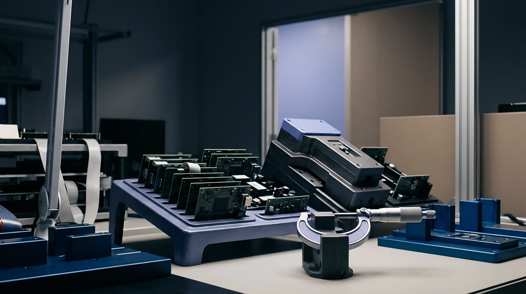
Topographical surface measurement tracks planar deformation across a printed circuit panel under thermal or mechanical loading. A planar deflection contour maps three-dimensional height variations across substrate arrays, identifying local bow and twist gradients. Metrology systems utilize shadow moire optical interferometers or digital fringe projection to capture surface height coordinates at elevated reflow temperatures.
Differential thermal expansion between copper layers and resin matrices causes dynamic warping during thermal profile passes. Uncontrolled dynamic deflection produces head-in-pillow defects, non-wetting open joints and solder paste bridging on high-density ball grid array components. Mapping surface height distributions pinpoints vulnerable areas where component co-planarity falls outside acceptable soldering thresholds.
Substrate manufacturers utilize contour data to optimize resin cure, copper balancing and core laminate selection.
Thermal Deformation
Dynamic warpage profiles alter board flatness continuously as temperature traverses preheat, soak, peak reflow and cooling phases. Asymmetrical copper balance across inner layers increases warpage severity, twisting the panel away from true flatness. Tooling supports and board carrier trays restrict panel distortion, helping to preserve planar alignment throughout high-temperature assembly cycles.
Reflow Acceptance
Acceptance thresholds defined in IPC-9641 establish allowable dynamic surface displacement for surface mount assembly. Process engineers reject panels that exceed allowable vertical deformation limits. Evaluating each planar deflection contour ensures solder joint integrity across large-format ball grid array packages.