Modeling High Frequency Phase Drift under Board Thermal Cycling Stress
Thermal expansion and dielectric coefficient shifts drive phase drift during temperature cycling, requiring matched CTE laminates and controlled foil profiles.
Thermal expansion and dielectric coefficient shifts drive phase drift during temperature cycling, requiring matched CTE laminates and controlled foil profiles.
Dynamic electrothermal permittivity drift shifts asymmetrical stripline impedance and phase velocity when uneven losses establish vertical heat gradients.
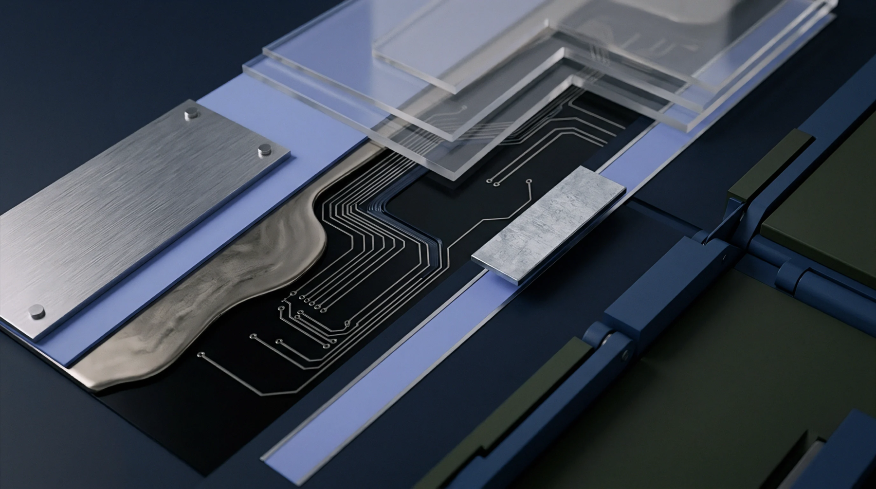
Spread glass eliminates micro-scale dielectric gradients across temperature, cutting phase velocity drift to under thirty parts per million per degree Celsius.
Asymmetric glass positioning offsets thermal Dk divergence between resin and yarn bundles, eliminating server channel phase skew without panel-wasting angled traces.
Substrate TcDK defines high-frequency phase and impedance drift across temperature, requiring ceramic-filled composites to prevent operational signal failures.
Match substrate TcDk and copper foil roughness on RF outer layers to cancel thermal phase velocity drift and maintain automotive radar target accuracy.
Split post resonators extract substrate temperature dielectric coefficients by separating thermal expansion dimensional changes from intrinsic permittivity drift.
Matrix thermal permittivity drift alters RF phase velocity and impedance, demanding ceramic-filled low-TcDk laminates for thermally stable millimeter-wave designs.
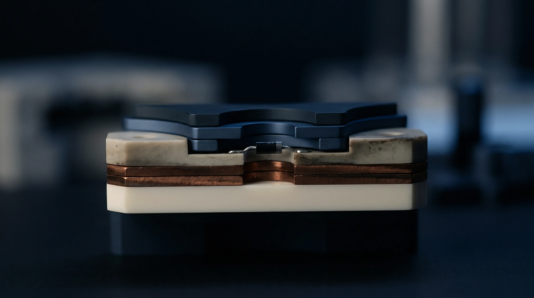
Substrate dielectric drift alters high-frequency signal phase velocity and impedance under thermal stress, requiring flat TCDk resin selection to hold timing margins.
Expertise is a utility, not a secret. sentiention™ publishes its working knowledge as open reference: intelligence layer covering the materials it sources, the markets it enters, and the reference that serves both.