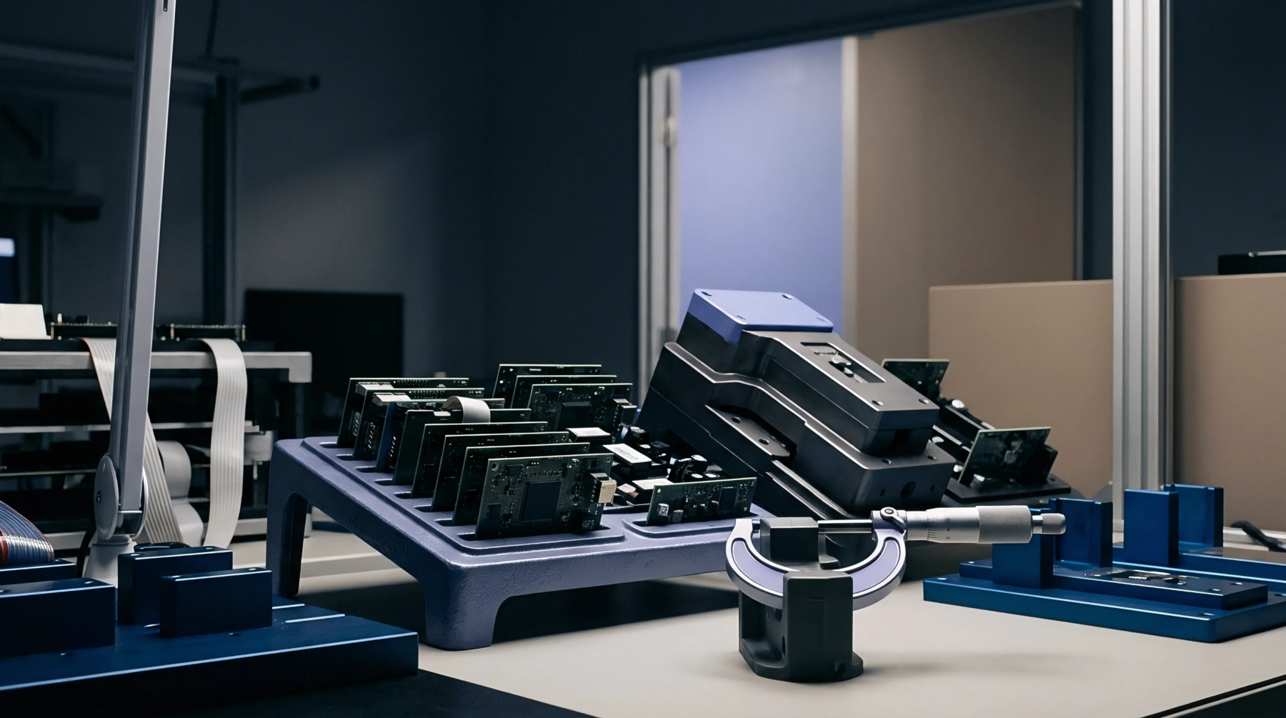
Mechanical Displacement
Local bending of printed circuit board substrates occurs when spring-loaded or locked pins exert force on the board during mounting or testing. Analyzing push pin deflection is critical to ensure that localized flexing does not damage delicate surface-mount components. This mechanical deformation can occur during test fixtures or under heat sinks.
Strain Profile
Strain gauges attached to the board surface measure the deformation of the FR4 laminate during test or assembly procedures. When push pin deflection exceeds a specific microstrain threshold, copper traces can tear or solder joints can rupture. The strain profile is influenced by the spacing of the support pins and the speed at which the load is applied.
Slower loading speeds or a larger number of support pins can distribute the load and reduce localized strains.
Joint Reliability
Fatigue failures in Ball Grid Array solder connections are directly linked to recurrent substrate bending during repetitive assembly operations. Excessive push pin deflection during testing can cause immediate failures or introduce latent defects that manifest as field returns later. Designers must calculate the maximum stress levels using finite element analysis to position supports where they prevent board flexure.
High reliability systems mandate that these mechanical stresses remain well below the fracture limit of SAC305 solder alloys.