Stress Acceleration
Electronic assemblies deployed in demanding operational environments endure repeated temperature fluctuations that induce thermomechanical stress across dissimilar material interfaces. Conducting a thermal cycling test subjects printed circuit board assemblies to controlled, repeated temperature swings inside specialized environmental chambers. Chamber controls adjust air temperature between specified lower and upper temperature extremes using controlled ramp rates and dwell durations.
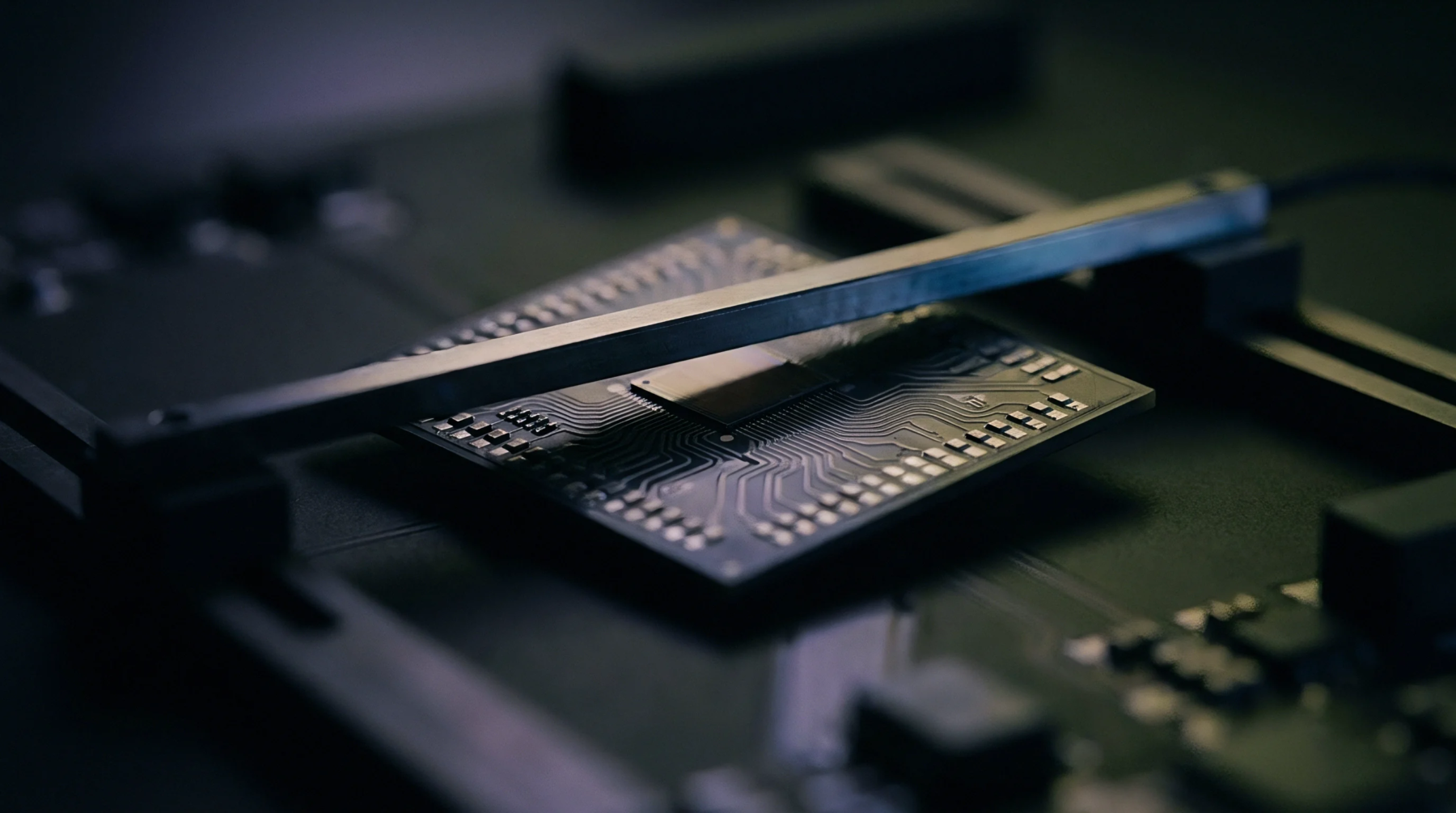
Continuous electrical monitoring measures trace continuity and solder joint resistance throughout temperature transitions to detect intermittent open circuits. Testing validates board construction materials, solder joint reliability, microvia structures and internal plated through-hole barrel integrity.
Fatigue Failure
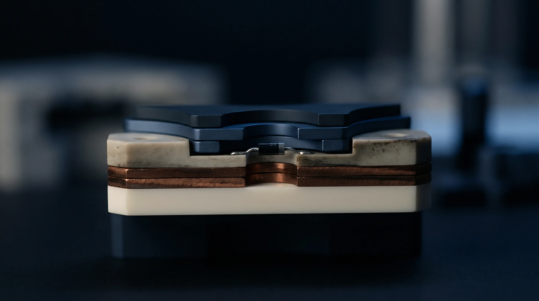
Thermal expansion mismatch between copper plating, laminate dielectrics, lead frames and ceramic component bodies drives creep fatigue damage during temperature swings. Executing a thermal cycling test accelerates microcrack initiation and propagation across solder joints and microvia structures. Failure analysis uses cross-sectional metallography to identify mechanical failure locations after thermal testing completes.
Reliability models extrapolate test cycle life data to predict operational field service lifetimes.
Test Boundary
Accelerated environmental stress profiles evaluate mechanical joint integrity and dielectric CTE mismatch but do not assess operational software functionality or high-voltage electrical breakdown limits. A thermal cycling test evaluates physical hardware robustness under environmental stress conditions. Quality standards establish minimum cycle thresholds for production lot qualification.