Thermal Reliability Test
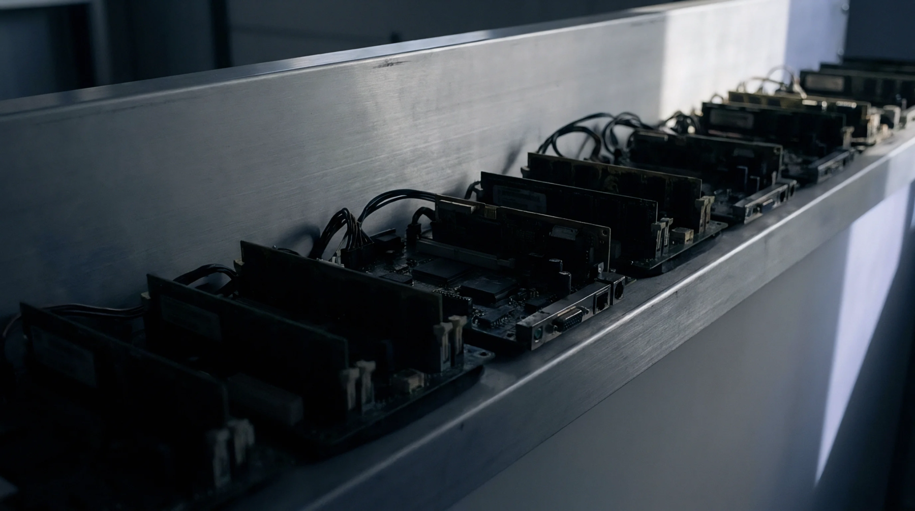
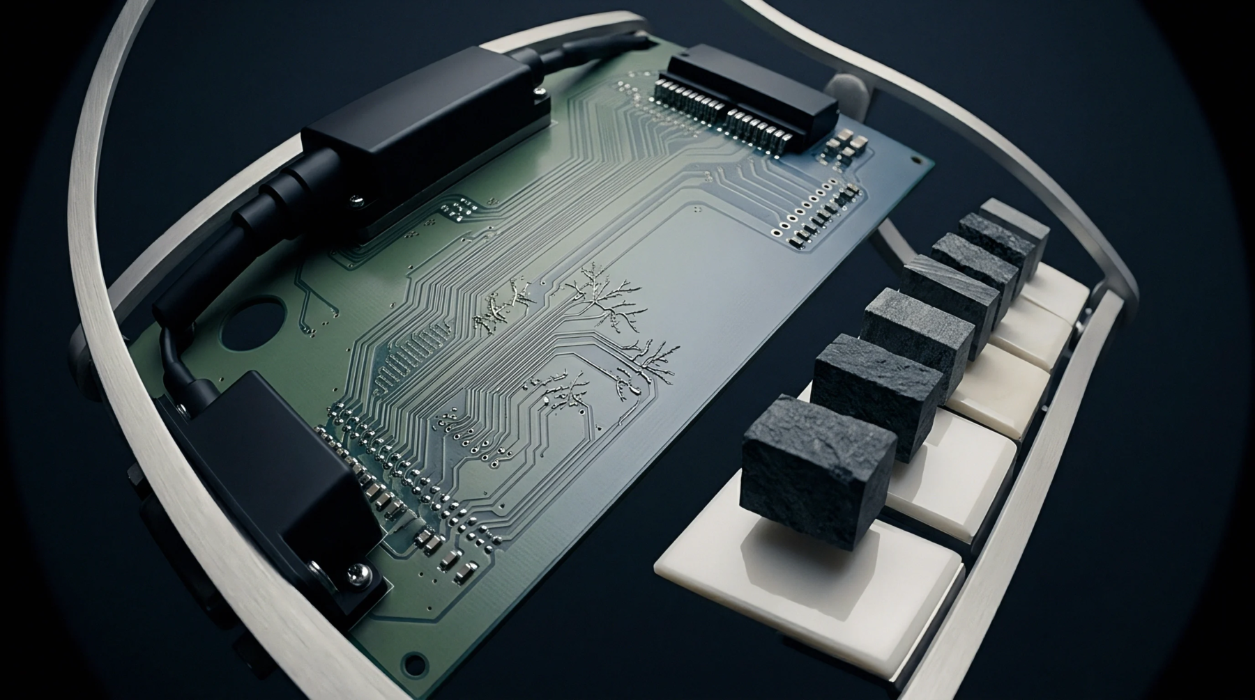
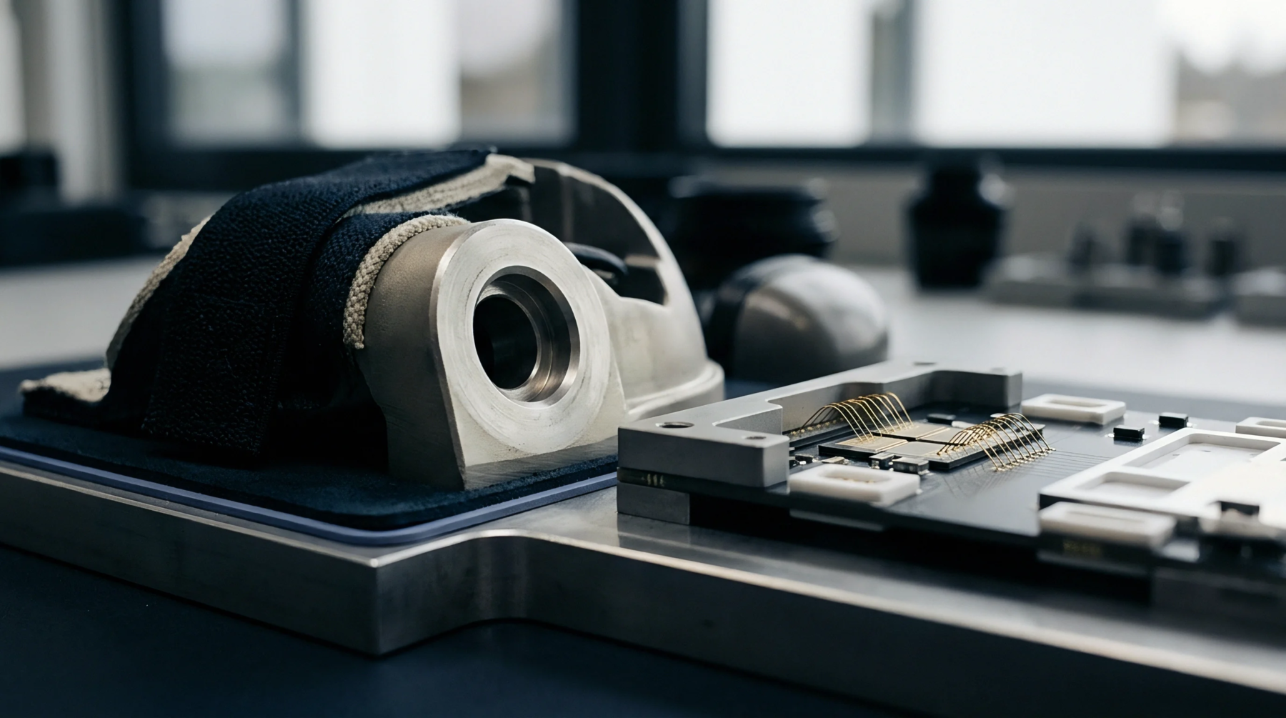
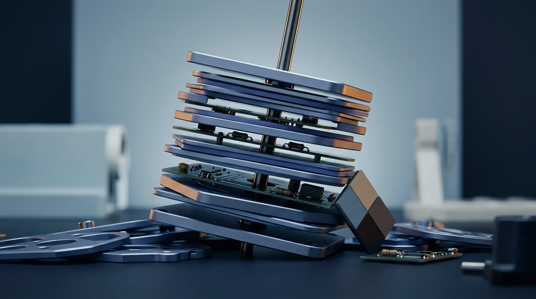
Environmental chamber exposure drives printed circuit board assemblies through controlled temperature extremes to quantify thermomechanical stress tolerance in solder joints and microvias. Engineers execute accelerated thermal cycling by ramping ambient temperatures between specified hot and cold dwell points, inducing cyclic shear strains due to coefficient of thermal expansion mismatches among silicon dies, substrate laminates and copper traces. Standard test profiles such as IPC-9701 enforce defined dwell times to allow complete stress relaxation in eutectic or lead-free solder alloys.
Thermal fatigue damages microstructures over repeated cycles until electrical resistance spikes confirm continuity failure.
Strain Rate Dynamics
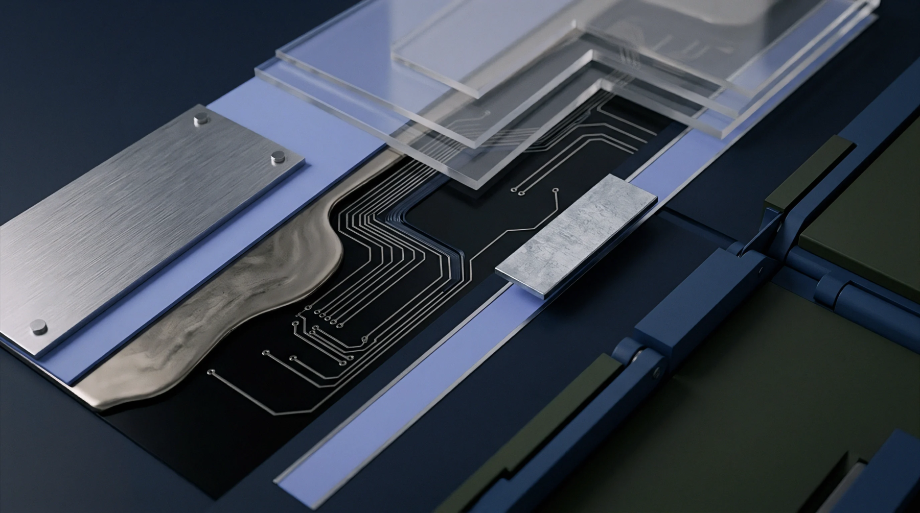
Rapid temperature shifts generate transient thermal gradients across complex assemblies that amplify local mechanical shear. During accelerated thermal cycling, differential expansion between copper plating and organic resin matrices causes microvia barrel cracking or corner cracked vias. The rate of temperature change dictates whether mechanical fatigue or creep damage dominates the degradation path.
Creep Saturation Limit
Dwell times extended beyond thirty minutes yield diminishing fatigue acceleration because solder strain relaxation reaches completion. Excessively steep thermal ramps introduce unrealistically high thermal shocks that trigger delamination modes absent during field operation. Qualification thresholds require continuous resistance monitoring during thermal testing to capture transient open circuits before cooling reseals cracks.