Mechanical Tolerance
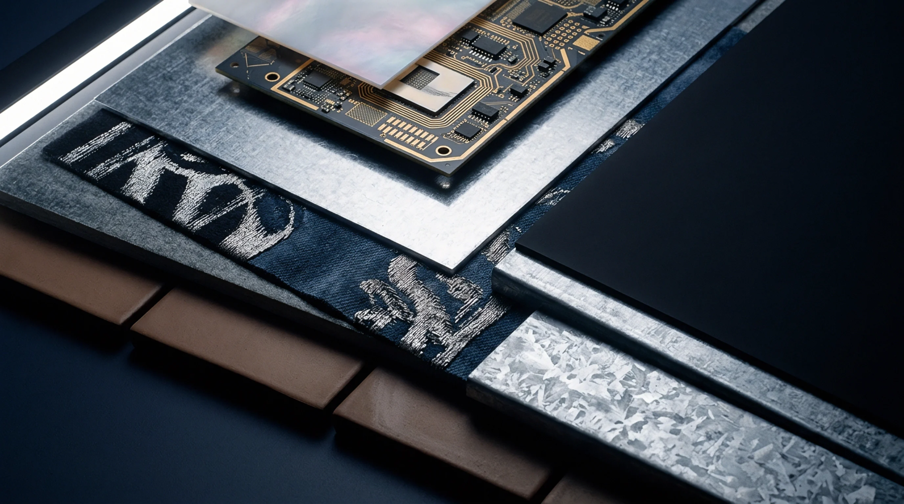
Structural deviation during printed circuit board fabrication governs assembly yield because mechanical warp alters surface planarity across a panel. Panel bow and twist measures maximum out of plane displacement relative to a theoretical reference plane defined by perimeter edges. Bow describes cylindrical or spherical curvature where all four corners lie in a single plane while two opposite edges rise above or fall below it.
Twist requires one corner to lift out of the plane defined by the other three corners, creating a saddle shape that prevents uniform solder paste deposition. Thermal stress applied during the press cycle of multilayer lamination introduces residual mechanical tension if glass cloth fill directions alternate incorrectly across the core. Subsequent exposure to infrared reflow ovens relieves this internal tension, causing the substrate to warp beyond acceptable limits before components arrive at the placement stage.
Assembly Consequence
Component placement machines rely on optical fiducial recognition systems that assume a flat surface geometry beneath the mounting head. When panel bow and twist exceeds a specific threshold, local height variations displace ball grid array packages vertically, leading to insufficient solder joint wetting or bridging defects. Rigid connector housings fail to seat flush against warped landing pads, producing open circuits after mechanical insertion forces relax.
Wave soldering pallets cannot clamp distorted substrates securely, allowing liquid solder to migrate onto top side circuitry through gaps created by edge lift. Automated optical inspection routines struggle to maintain consistent focus across a severely deformed substrate, generating false failure flags due to perspective distortion in the captured image.
Acceptance Standard
Industrial manufacturing specifications establish a maximum allowable out of plane displacement percentage calculated against the diagonal dimension of the bare circuit board. IPC standards restrict standard surface mount technology panels to a maximum warp of seventy five percent for rigid boards, while thinner flex hybrid constructions operate under stricter thresholds. Optical shadow Moiré measurement systems project fringe patterns onto the heated panel surface to map contour displacement gradients without physical contact.
Mechanical dial indicators mounted on granite inspection tables verify edge clearance when the board rests unrestrained on a three point support fixture. Rejection criteria depend entirely upon the density of fine pitch devices scheduled for subsequent attachment, because tighter pitch architectures tolerate far less planar deviation than legacy through hole assemblies.