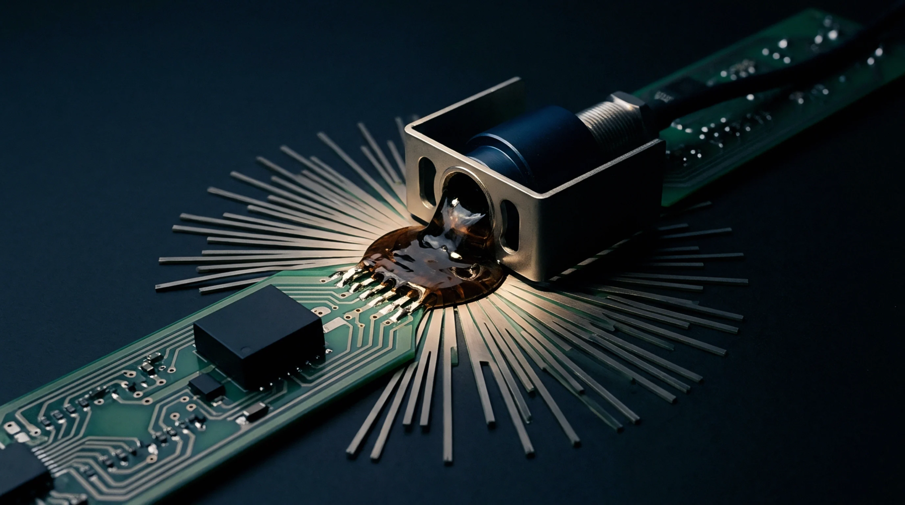
Fatigue Failure
Mechanical failure modes in electronic assemblies occur when cyclic thermal or mechanical stress initiates and propagates fractures through the interconnect material. The development of solder joint cracking is one of the most common causes of electrical failure in printed circuit boards. These fractures break the copper-to-component path, causing intermittent open circuits or complete system failure.
This defect often originates at the outer edges of the joint where the shear stress is concentrated, making early detection difficult without specialized tools.
Stress Source
Thermal expansion differences between the component package and the fiberglass substrate generate continuous shear stress during operation. When the board heats up, a silicon chip with a low coefficient of thermal expansion expands less than the epoxy-glass substrate, forcing the connecting solder joint to deform plastically. Over multiple temperature cycles, this plastic deformation leads to microstructural coarsening, where the tin grains grow and accumulate defects along their boundaries, ultimately resulting in solder joint cracking.
This degradation is accelerated in lead-free assemblies like those using SAC305, because the higher rigidity of the alloy transmits more energy to the intermetallic interface, which is inherently brittle. The crack typically propagates through the bulk solder or directly along the copper-tin intermetallic boundary, depending on the peak temperature and mechanical strain rates.
Diagnostics Technique
Inspection techniques must utilize high-resolution imaging and electrical testing to identify these fractures before products reach final assembly. While visual inspection can detect large surface-breaking cracks, x-ray inspection and transient acoustic testing are required to locate internal separation under ball grid arrays. Dye-and-pry testing is a highly effective destructive method where a red dye is drawn into the crack, allowing the joint to be mechanically pried open to reveal the colored crack surface.
Applying these diagnostic techniques during design validation ensures that component layouts are robust against expected operational stresses.