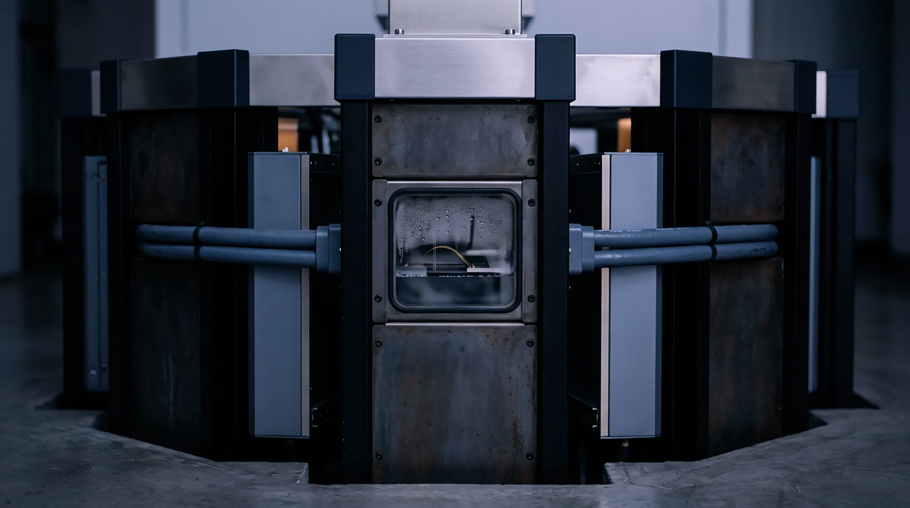
Nailbed Architecture
Electrical verification operates through physical probe contact against test pads on a completed printed circuit board assembly. In-circuit test brings fixed spring pins down onto solder joints and component leads to measure resistance, capacitance and junction behavior independently. Automated equipment applies small voltages to specific nodes while guarding surrounding traces to isolate passive components from parallel paths.
This process detects missing parts, reversed diodes and open solder joints before boards leave the factory floor. Production engineers design dedicated mechanical fixtures matching the exact coordinate layout of each circuit board design. Fixture fabrication requires extreme mechanical precision to ensure every needle strikes its intended target without slipping off microscopic lands.
Fault Resolution
Diagnostic software translates raw resistance thresholds into specific component failures displayed on an operator monitor. Technicians review node shorts and open circuits identified during the probe cycle to locate manufacturing defects introduced during surface mount placement or wave soldering. Repair stations use these precise coordinate readouts to rework faulty solder joints or replace damaged passive devices.
Defect data feeds back into preceding printing and placement operations to correct systemic alignment errors before large quantities accumulate.
Boundary Condition
Testing limits arise when parallel circuitry prevents complete isolation of individual components by the measurement hardware. Dense multi-layer board designs restrict physical access by reducing available surface area for dedicated test pads beneath components. Engineers must add boundary scan test chains to supplement physical probing where direct nailbed contact proves impossible due to miniaturization constraints.
High frequency analog sections often require functional testing rather than static probe checks because component values shift under operational power conditions.