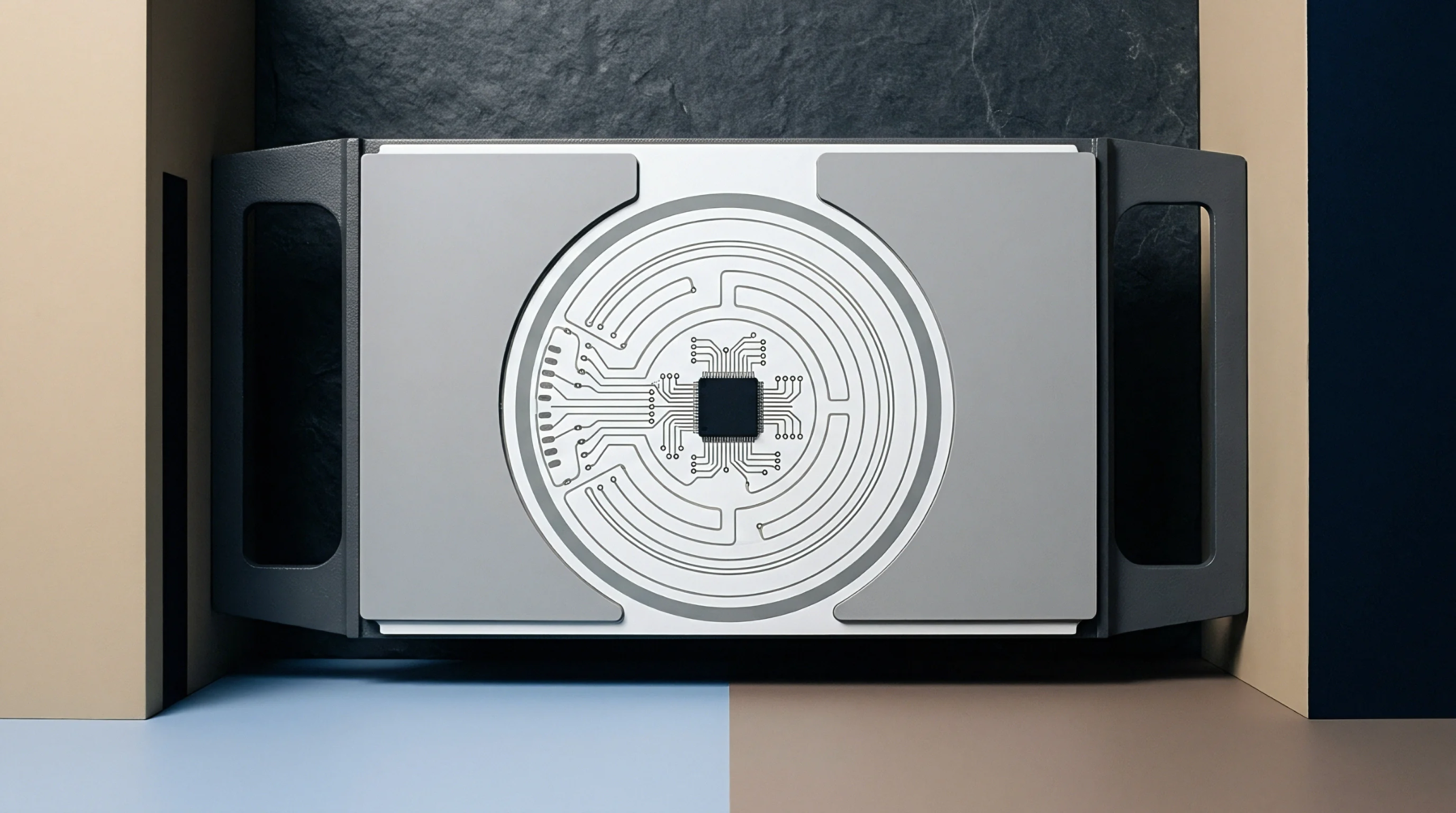
Trace Geometry
Electrical conductor paths angled across a dielectric substrate mitigate signal crosstalk and reduce parasitic capacitive coupling between parallel runs. This zig-zag routing technique offsets the parallel orientation of traces on adjacent layers or within the same signal plane. High frequency signals benefit from the reduction in electromagnetic interference that occurs when long parallel runs remain in proximity.
Design software implements these angular shifts automatically by adjusting the etch path according to predefined constraints.
Signal Integrity
Electromagnetic field containment relies on the physical separation of current return paths from signal conductors. When traces follow a zig-zag routing pattern, the varying distance between traces forces a change in the impedance profile along the length of the conductor. Engineers manage this effect by keeping the angular offset consistent to avoid localized signal reflection.
Precise impedance control requires careful matching of the dielectric thickness and the width of the trace as the angle changes. Ground plane continuity remains the priority during the placement of these angled segments.
Manufacturing Verification
Fabrication shops inspect board layers for etched geometry errors that might result from aggressive angular routing near tight clearances. Automated optical inspection equipment detects trace thinning or bridging at the vertices of these angles where the etching chemistry potentially pools. Consistent clearance between the angled edges of the conductor and adjacent pads determines the reliability of the finished board during high voltage testing.
Manufacturers adjust the etch factor compensation parameters to account for the increased copper surface area at the corners of these traces. Proper execution of the pattern ensures the finished circuit performs to the specified frequency requirements without mechanical stress at the bend points.