Evaluating Step Stencil Keep out Zones for Mixed Pitch Assemblies
Step stencil keep out zones require a 10 to 1 distance ratio per mil of step height difference to prevent squeegee levitation and solder paste bridging.
Step stencil keep out zones require a 10 to 1 distance ratio per mil of step height difference to prevent squeegee levitation and solder paste bridging.
Calculate stencil area ratio above 0.66 for standard laser foil and above 0.50 for nano coated electroformed stencil to guarantee ninety percent paste release.

Calculating area ratios above 0.66 and applying targeted aperture reductions prevents bridging while ensuring consistent solder paste transfer efficiency on fine pitch pads.
Thixotropic rebuild kinetics dictate stencil release and deposit stability, where tuning separation speed to viscosity recovery maximizes fine pitch print yield.

Excessive squeegee speed and downforce over-shear solder paste, reducing yield stress and causing severe deposit slump and bridging on fine-pitch components.

Verify stencil aperture area ratios exceed 0.66 using SPI volume data before adjusting reflow oven profiles for solder starvation defects.
Electroformed nickel stencils lower aperture wall roughness below 0.08 µm Ra, enabling clean solder paste release at area ratios down to 0.50 for 0.3mm BGAs.

Stencil thickness selection balances aperture area ratios above 0.66 with component paste volume demands to eliminate SMT print defects and maximize yield.
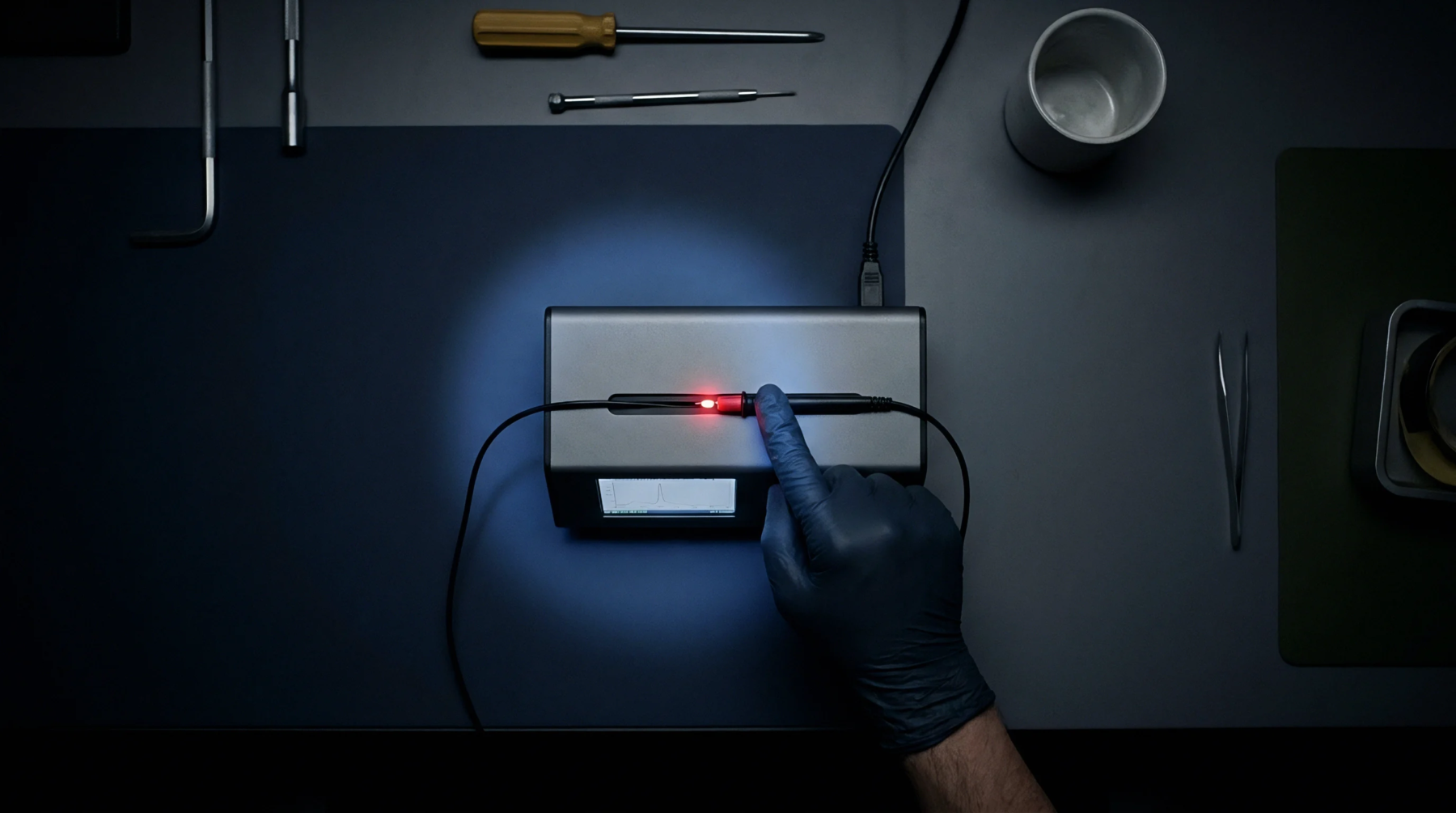
Optimize solder paste print volume and yield by maintaining area ratios above 0.66, controlling squeegee force, and verifying viscosity stability.
Expertise is a utility, not a secret. sentiention™ publishes its working knowledge as open reference: intelligence layer covering the materials it sources, the markets it enters, and the reference that serves both.