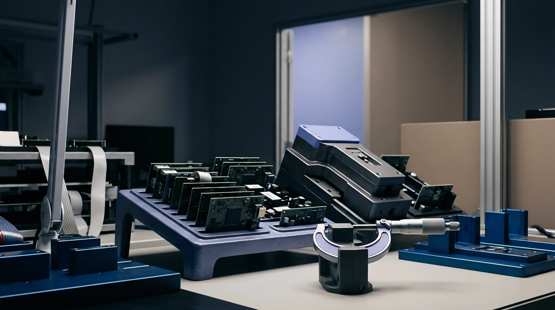
Electroplated Dimension
Applied metallic coating thickness during mass component finishing defines the dimensional boundary of printed circuit board through hole metallization and surface contact pads. Barrel plating thickness specifies the vertical deposition rate and current distribution limit for small components tumbled inside a rotating cathodic cylinder. Excess metal accumulation inside the containment vessel bridges adjacent contacts and creates solder shorts during subsequent printed circuit board assembly.
Insufficient deposit coverage exposes underlying copper to oxidation and compromises intermetallic bond formation during reflow soldering. Process engineers control this deposit dimension by adjusting bath chemistry, rotation speed, and applied current density. Microscopic cross sectioning under optical magnification verifies actual metal thickness against drawing specifications before batch release.
Variations in component geometry create localized current shielding inside the processing load. Parts located near the outer periphery receive higher current density than components trapped in the center of the rotating mass.
Deposition Variance
Plating bath chemistry temperature and chemical additions govern grain structure growth rates during the electrolytic reduction phase. Metallic ions migrate through solution paths inside the rotating vessel under direct current influence. Current efficiency drops when brightener concentrations exceed operational limits within the chemical tank.
Hull cell testing identifies optimal additive ranges before production runs commence. Cathodic efficiency calculations predict metal deposition rates based on active surface area measurements. Overloading the containment vessel restricts solution exchange and produces uneven coating profiles across the batch.
Low rotation speeds cause part nesting where component surfaces mask neighbors from ionic current flow. Operators monitor bath chemistry parameters continuously to maintain stable deposition kinetics.
Acceptance Boundary
Final inspection protocols reject batches exhibiting uneven metal distribution or structural porosity within the metallic layer. Standard cross section analysis measures local deposit thickness at multiple points across sampled components. Compliance with drawing requirements ensures reliable electrical performance and mechanical durability during downstream surface mount operations.
Surface contamination prevents uniform adhesion between the base copper and the deposited metallic layer. Thermal shock testing reveals microstructural defects resulting from improper plating parameters or inadequate cleaning steps. Production facilities establish internal control limits tighter than absolute drawing limits to guarantee manufacturing yield.
Completed assemblies pass rigorous electrical continuity checks when constituent parts maintain specified coating dimensions throughout the manufacturing cycle.