
Target Impedance Modeling for High Frequency Power Plane Stackups
Target impedance modeling defines maximum power rail impedance limits across frequency to suppress transient voltage ripple through thin plane cavity stackups.
Target impedance modeling defines maximum power rail impedance limits across frequency to suppress transient voltage ripple through thin plane cavity stackups.
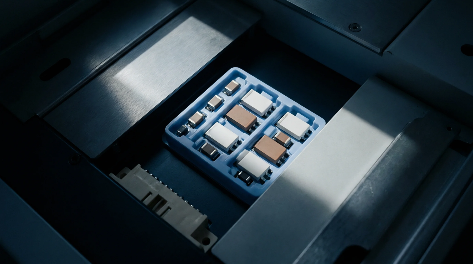
Analyse power plane cavity modes using 2D wave equations and two-port VNA impedance tests to damp resonant impedance spikes below target limits.

Sub-milliohm substrate resistance shifts trigger severe current crowding across microbump arrays, demanding high-precision thermal and magnetic screen metrology.

Predicting high-frequency plane radiation requires Monte Carlo modeling of capacitor tolerances to ensure power distribution networks pass CISPR 32 limits.

Calibrated two-port shunt-through VNA measurements require cable shield choke isolation and de-embedded fixture planes to resolve milliohm rail impedance accurately.

Plane cavity resonances create target impedance spikes that demand dampening vias, controlled ESR capacitors, and calibrated two-port VNA testing.

Suppression of plane cavity resonance relies on sub-lambda via fences, thin-core laminates, and edge damping to eliminate impedance peaks and radiated emissions.

Thin dielectric power plane pairs suppress high frequency cavity modes and radiated emissions by lowering target impedance and shifting resonant frequencies.
Mapping high-speed power rail transfer impedance limits directly to radiated emissions limits prevents costly EMC chamber re-tests and batch rejections.
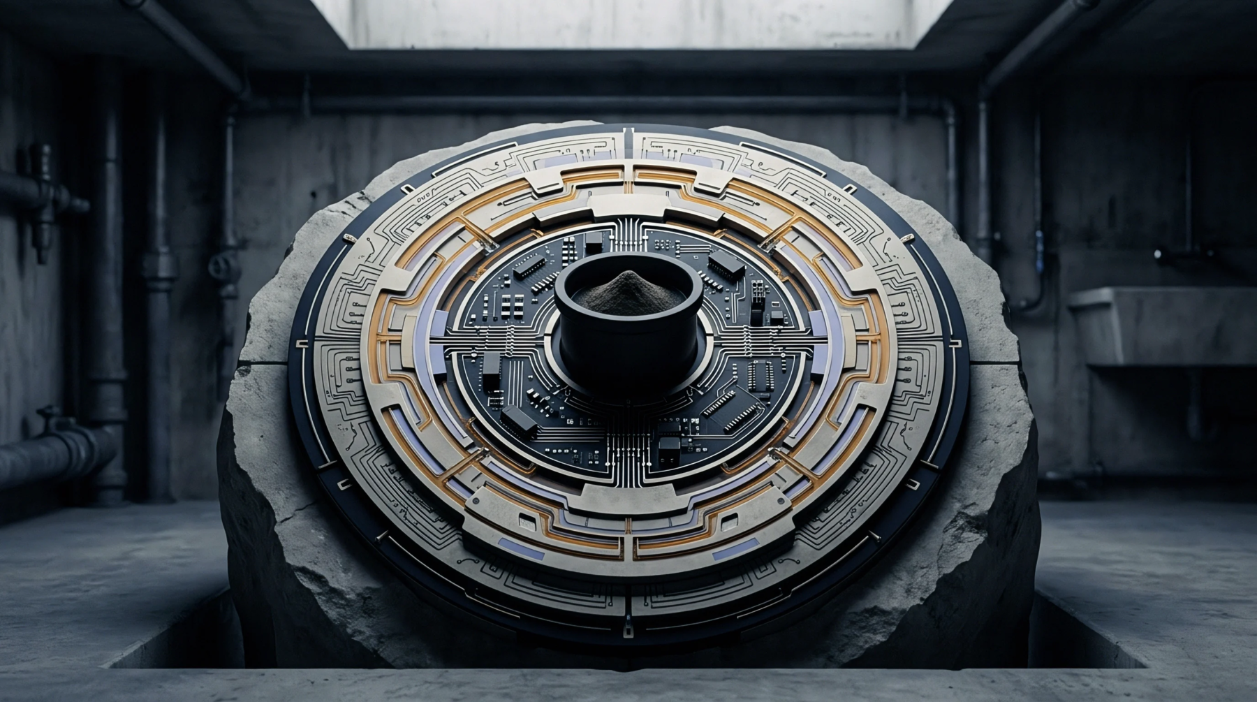
Power distribution plane cavity resonances create high impedance peaks that drive edge fringing fields, forcing radiated emissions beyond CISPR 32 limits.
Expertise is a utility, not a secret. sentiention™ publishes its working knowledge as open reference: intelligence layer covering the materials it sources, the markets it enters, and the reference that serves both.