Thermal Design
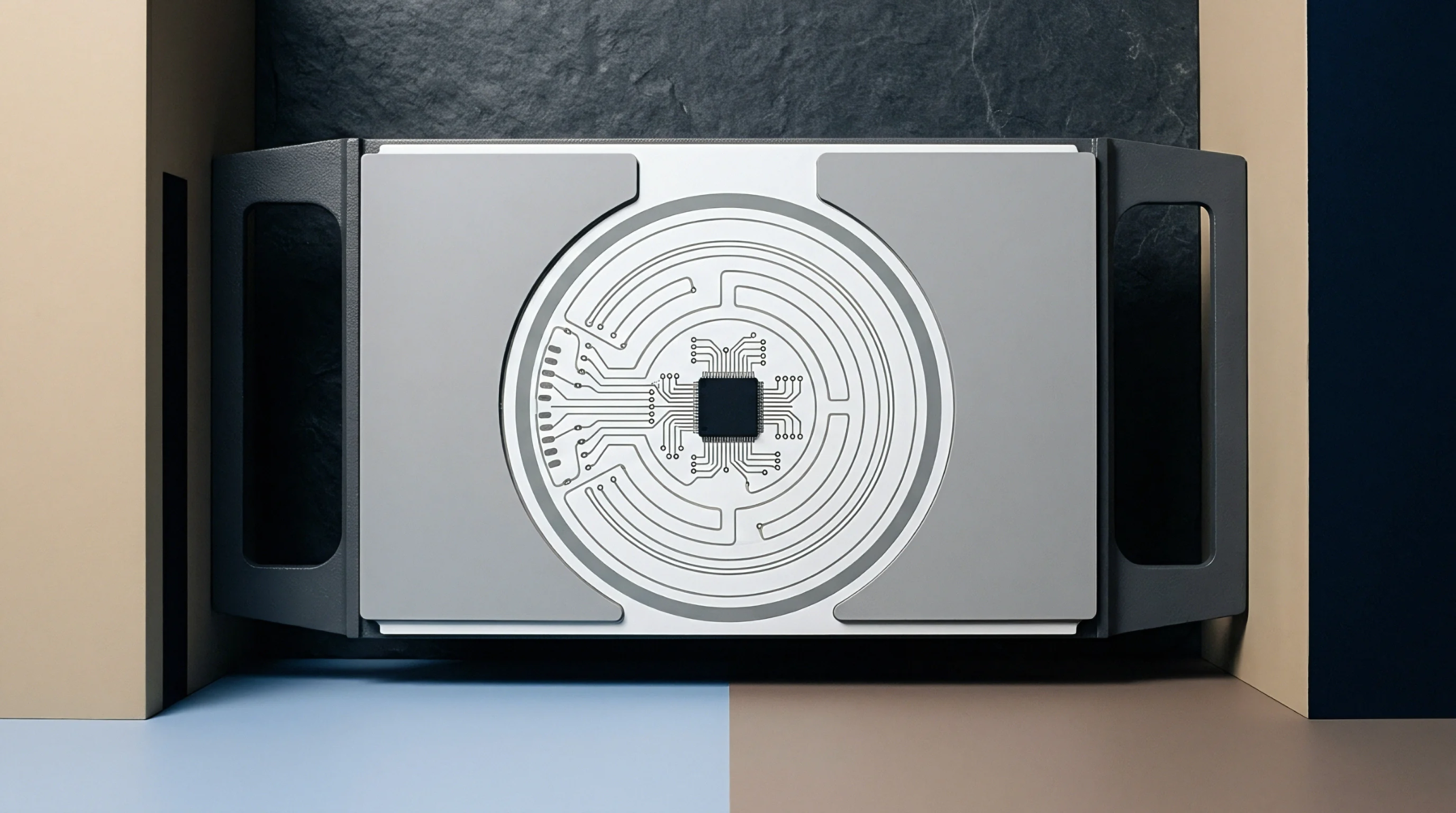
IPC-7093 defines the accepted design and assembly guidelines for bottom termination components in modern printed circuit boards. Thermal performance relies heavily on how effectively solder joint voids are managed underneath large central pads during surface mount manufacturing. Solder paste volume and stencil aperture patterns dictate whether trapped gas escapes before reflow solidifies the joint.
Proper void percentage limits prevent premature thermal fatigue during operational cycles. Designers must balance electrical grounding requirements against the need for adequate thermal transfer paths through the internal board layers. X-ray inspection systems capture sub-surface void distribution after reflow to verify compliance with assembly standards.
Excessive voiding reduces the cross-sectional area available for heat dissipation, leading to localized hot spots and eventual solder joint cracking.
Assembly Process
Reflow profile optimization dictates the heating and cooling rates that allow volatile solvents to outgas safely from the solder paste matrix. Stencil thickness and multi-zone aperture segmentation prevent flux entrapment by creating dedicated escape channels for gaseous byproducts. Component placement pressure forces excess paste outward into peripheral voids or relief zones before thermal ramp begins.
Nitrogen reflow atmospheres lower surface tension, aiding the collapse of paste deposits into a continuous joint structure. Production lines monitor thermal profiles using sacrificial test boards equipped with thermocouples embedded directly beneath the central thermal pad. Paste manufacturers formulate specific powder alloy distributions to minimize outgassing phenomena during the critical preheat stage.
Reliability Validation
Thermal cycling tests subject completed assemblies to extreme temperature swings, driving mechanical stress into the boundary layers where component packages meet the substrate. Shear testing measures mechanical strength after exposure to environmental conditioning, confirming that joint integrity satisfies structural demands. Microsection analysis reveals grain boundary structures and intermetallic layer formation within the solidified solder alloy.
Assemblies failing thermal performance criteria typically exhibit crack propagation originating at large void boundaries within the central ground pad connection. Field failures occur when operational power dissipation exceeds the heat rejection capacity of the internal board planes, causing thermal runaway in the silicon die. Long term reliability depends on maintaining strict process control over paste deposition and stencil design parameters throughout volume production.