How a Printed Circuit Board Is Built Layer by Layer
Multilayer PCB fabrication laminates etched copper cores and prepreg under heat and vacuum, creating vertical interconnects through precision drilling and copper electroplating.
Multilayer PCB fabrication laminates etched copper cores and prepreg under heat and vacuum, creating vertical interconnects through precision drilling and copper electroplating.
Stackup selection balances resin flow, z-axis dielectric constants, and panel utilization to fix bare-board cost, impedance tolerances, and factory pool.

Peripheral coupon TDR reports require empirical offset adjustments derived from physical microsections to accurately reflect functional internal board impedance.

Mechanically spread glass fabrics flatten yarn bundles to eliminate resin-rich windows, stabilizing relative permittivity and preventing high-speed differential skew.

Spatial dielectric variation in glass laminates stems from weave periodicity and drives phase skew, requiring spread glass or angled routing to pass tight jitter budgets.

Mid-loss laminates paired with low-roughness copper foil match high-cost ultra-low-loss performance at a fraction of the raw panel price.
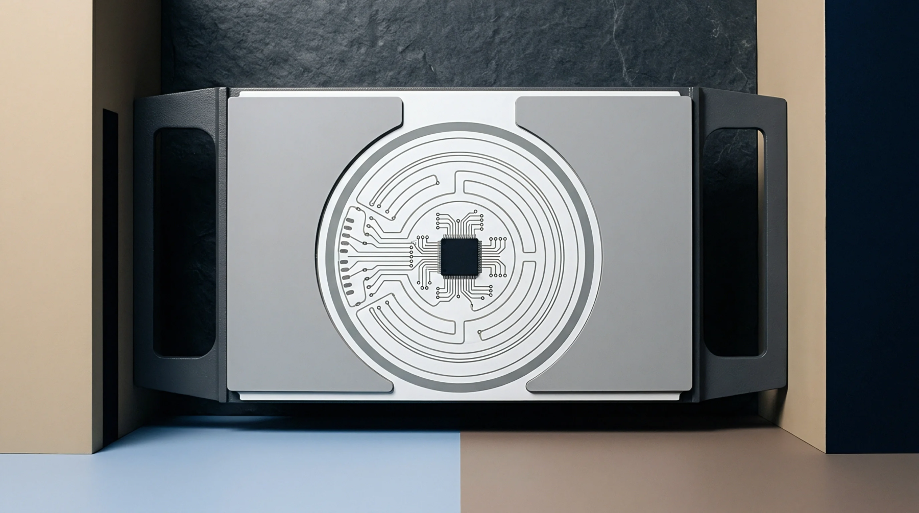
Spread glass prepreg selection eliminates differential phase skew by flattening fiber bundles and reducing dielectric constant variations across signal paths.

Controlled impedance across rigid flex transitions requires matching dielectric constants, tapering trace widths, and maintaining continuous ground planes.
Adhesiveless hydrophobic polyimide interfaces reduce high-frequency dielectric attenuation by suppressing moisture uptake and eliminating lossy acrylic adhesive layers.
Multilayer directional permittivity variance causes stripline capacitance shifts that must be corrected by modeling in-plane and out-of-plane dielectric constants separately.
Mid-loss laminates optimize high-speed signal reach between 5 and 28 Gbps by controlling dielectric loss without imposing low-loss fluoropolymer costs.
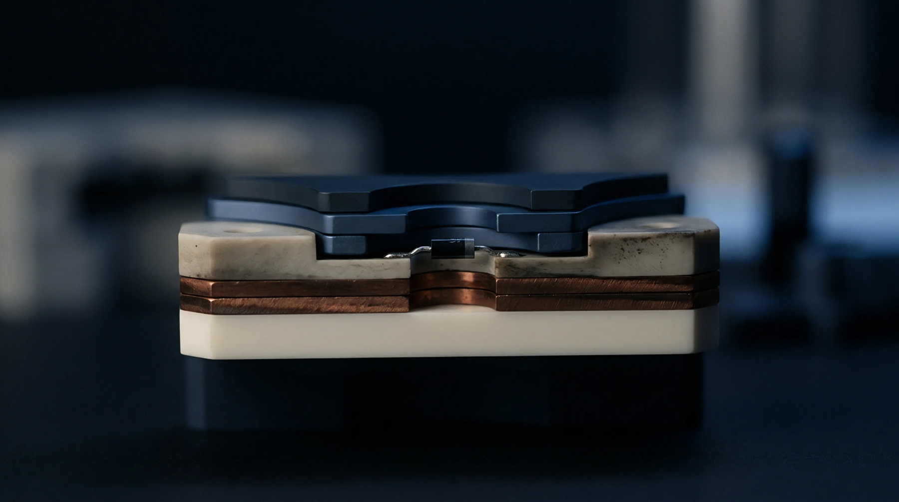
Substrate dielectric drift alters high-frequency signal phase velocity and impedance under thermal stress, requiring flat TCDk resin selection to hold timing margins.

Sub-50 micron trace etching demands mSAP seed layers, anisotropic chemistry passivators, and dynamic laser imaging scaling to hold 3.5+ etch factors and pass IPC Class 3 yield limits.
Selecting dielectric substrates requires balancing dissipation factor, glass weave uniformity, foil roughness, and panel yields to meet high-speed impedance targets.

Stackup thickness control requires calculating pressed prepreg heights over local copper patterns to hold impedance and microvia drilling tolerances.

Selecting mechanically spread glass fabric and enforcing multi-ply laminate construction mitigates intra-pair differential skew without panel rotation costs.
Optimize hybrid PCB fabrication by matching laminate cure kinetics, deploying plasma desmear for mixed resins, and applying layer-specific scaling factors.
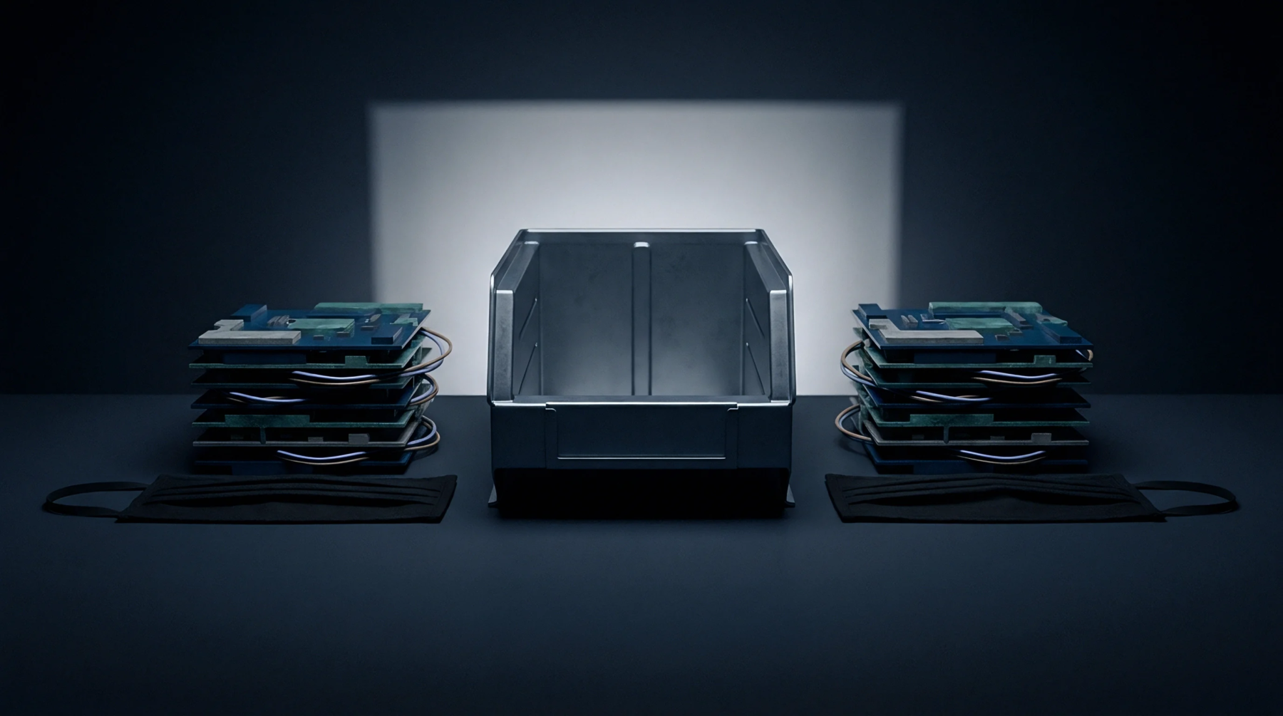
IPC-4101 slash sheets establish mandatory baseline physical, thermal, and electrical limits that override generic trade names to enforce material reliability.
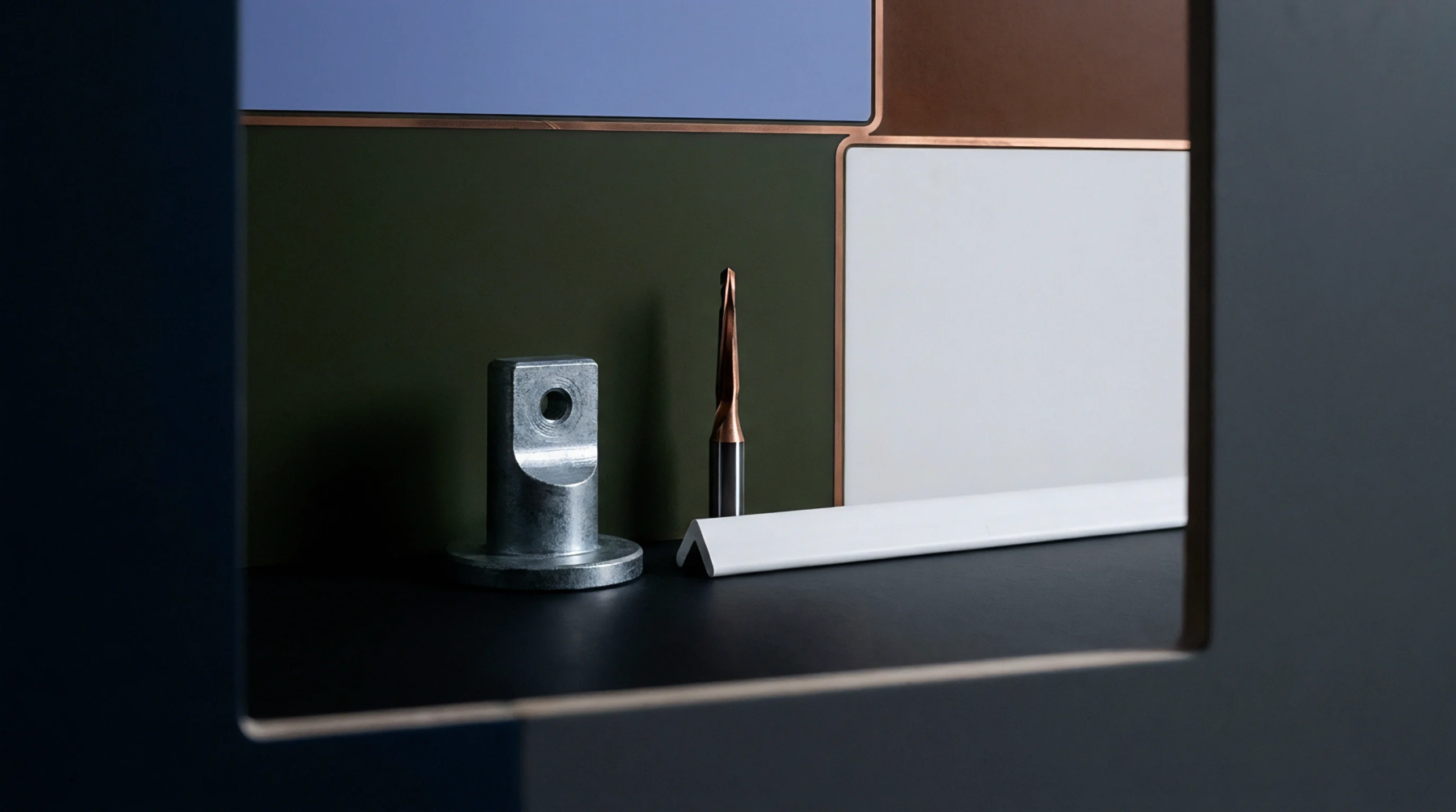
Pairing mid-loss resins with HVLP copper cuts high-frequency trace attenuation by up to 38 percent without forcing transitions to expensive ultra-low-loss substrates.
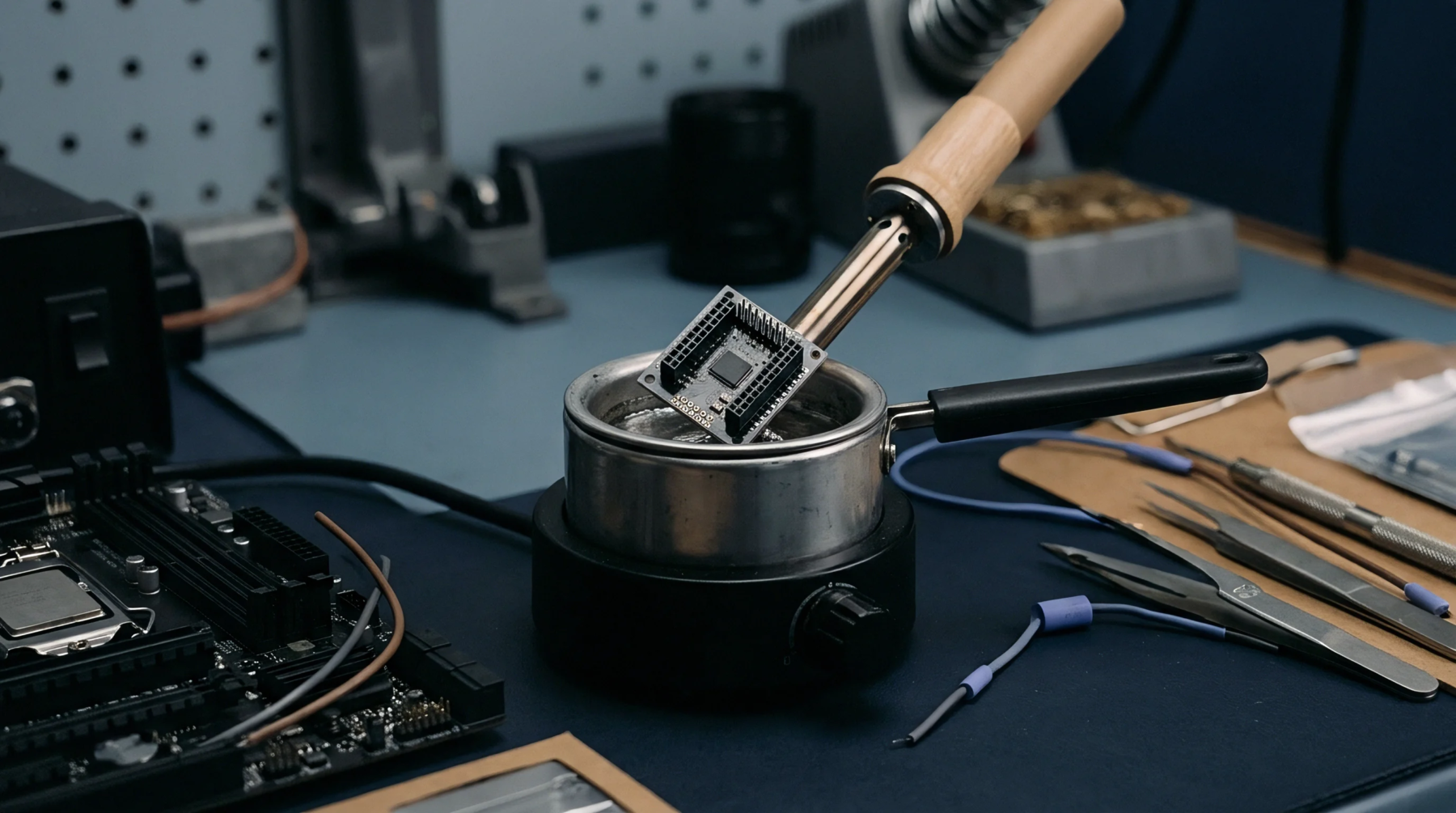
Aligning glass yarn warp directions parallel across every stackup layer prevents asymmetric dimensional shrinkage and eliminates structural panel twist during lamination.

Mitigate sub-core microvia target pad delamination by enforcing eighteen-micrometre foils, controlled microetching, and staggered layout architectures.
ENIG guarantees 24-month solderability for staggered assembly runs, while OSP degrades beyond six months unless stored in vacuum-sealed moisture barrier bags.
Spread prepreg styles flatten glass yarns to eliminate dielectric window voids, reducing differential phase skew below 1.5 ps per inch in PAM4 signal lines.
Quasi-optical extraction isolates intrinsic substrate loss from copper roughness, requiring explicit z-axis anisotropy conversion for accurate mmWave stackup design.

Reinforcement fiber bundle periodicity causes localized dielectric constant variation, driving phase skew that requires spread glass or rotated routing to control.
Dynamic phase calibration models calculate coupled thermal permittivity and physical expansion shifts to eliminate skew across heterogeneous interconnect stackups.

Optimizing rigid-flex stackups for high-speed signals requires adhesiveless polyimide cores, cross-hatched reference alignment, and staggered rigid transitions.
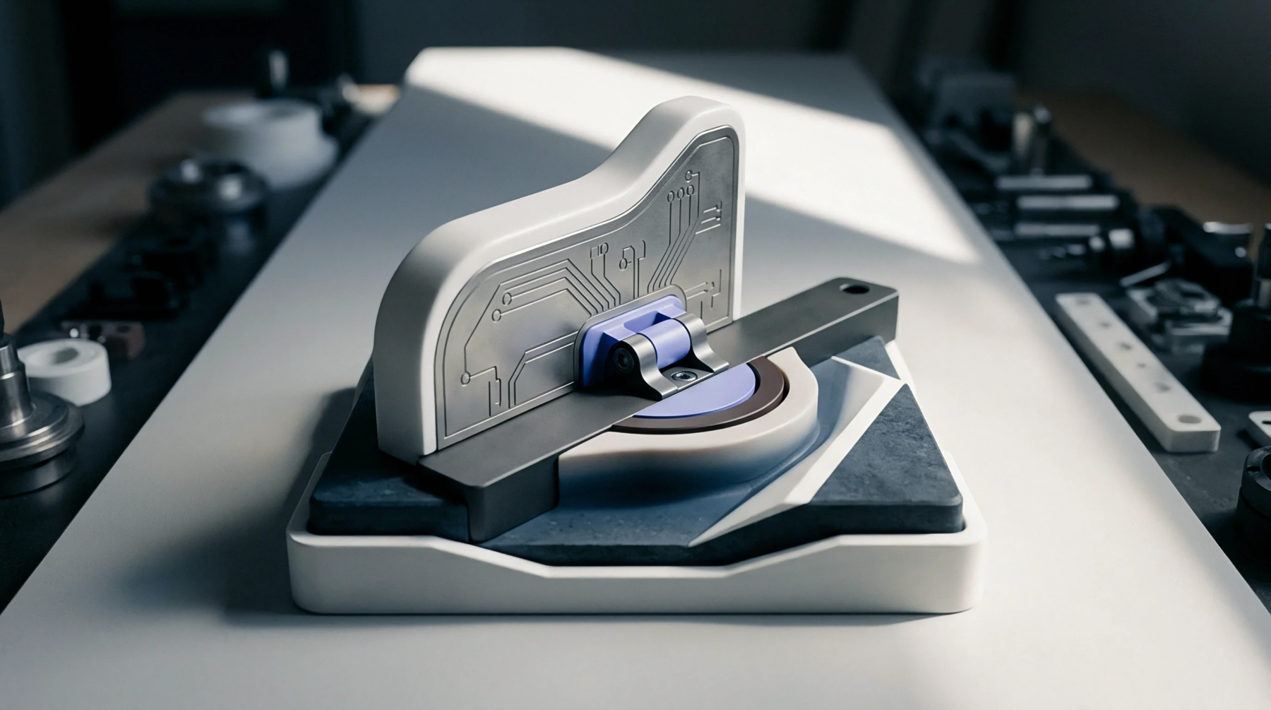
Adhesiveless polyimide substrates eliminate high-loss acrylic adhesives, dropping dielectric loss tangents to 0.002 at 10 GHz when paired with smooth rolled copper.
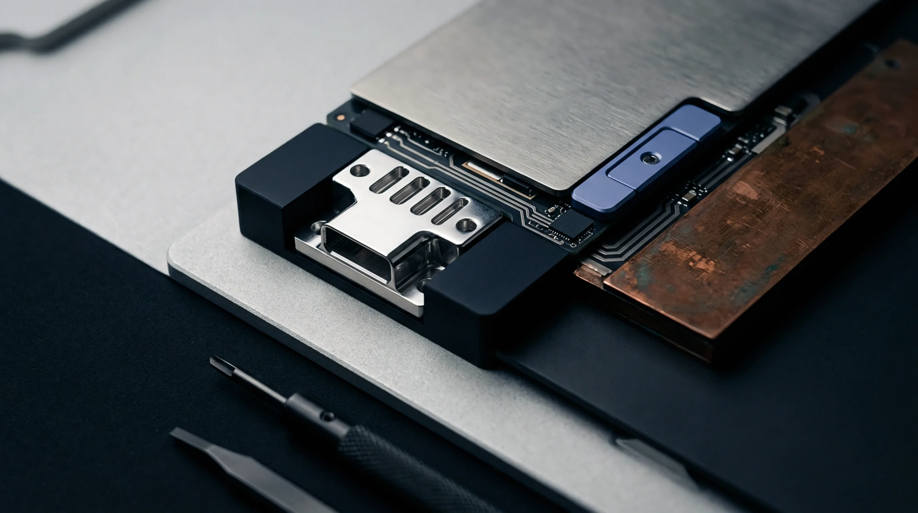
Dynamic viscosity minimums and hydraulic press profiles dictate complete microscale clearance filling, preventing latent internal voids and panel scrap.

Mid-loss laminates balance dissipation factors between 0.005 and 0.010 with moderate panel costs, matching PCIe Gen 4 and 10GbE signal integrity demands.
Expertise is a utility, not a secret. sentiention™ publishes its working knowledge as open reference: intelligence layer covering the materials it sources, the markets it enters, and the reference that serves both.