Mid Loss Laminate Selection Criteria for High Speed Circuits
Mid-loss laminates optimize high-speed signal reach between 5 and 28 Gbps by controlling dielectric loss without imposing low-loss fluoropolymer costs.
Mid-loss laminates optimize high-speed signal reach between 5 and 28 Gbps by controlling dielectric loss without imposing low-loss fluoropolymer costs.
Controlling master panel resin flow gradients stabilizes dielectric tensor anisotropy and prevents high-frequency parametric yield collapse.
Air gap corrections eliminate systematic two to six percent dielectric underestimation in clamped stripline tests, preventing finished board impedance failures.
Thermal expansion alters resin density, driving dynamic anisotropy shifts that detune millimeter-wave phase stability and coupling tolerances across temperature.
IPC-4101 slash sheets establish mandatory baseline physical, thermal, and electrical limits that override generic trade names to enforce material reliability.
Lead-free reflow shifts substrate permittivity by altering free volume and desorbing moisture, changing line impedance by up to 2.5 ohms on high-speed traces.
Anisotropic dielectric tensor modeling eliminates up to 8 ohm trace impedance errors and timing skew in high speed package substrates compared to isotropic models.
Dielectric characterization methods determine in-circuit signal velocity by accounting for test fixture field structure, glass anisotropy, and copper surface roughness.
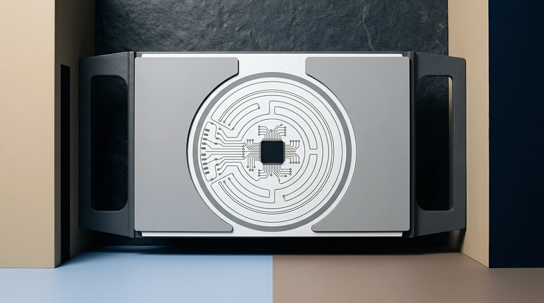
Glass weave skew causes intra-pair phase delay in high-speed differential pairs, requiring spread glass, dual-ply prepreg, or off-axis panel rotation.
Selecting mechanically flattened spread glass styles like 1067 or 1078 eliminates dielectric pitch gaps and keeps high-speed differential skew below 2 ps/inch.
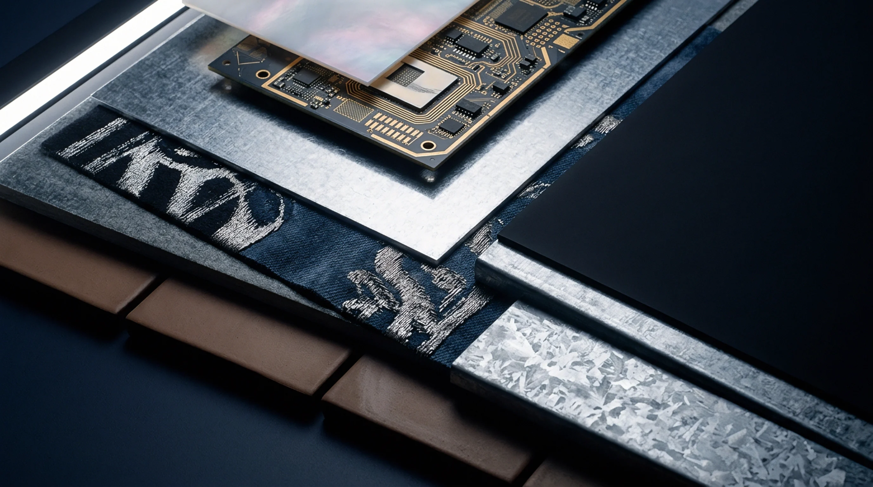
Quasi-optical extraction isolates intrinsic substrate loss from copper roughness, requiring explicit z-axis anisotropy conversion for accurate mmWave stackup design.

Reinforcement fiber bundle periodicity causes localized dielectric constant variation, driving phase skew that requires spread glass or rotated routing to control.
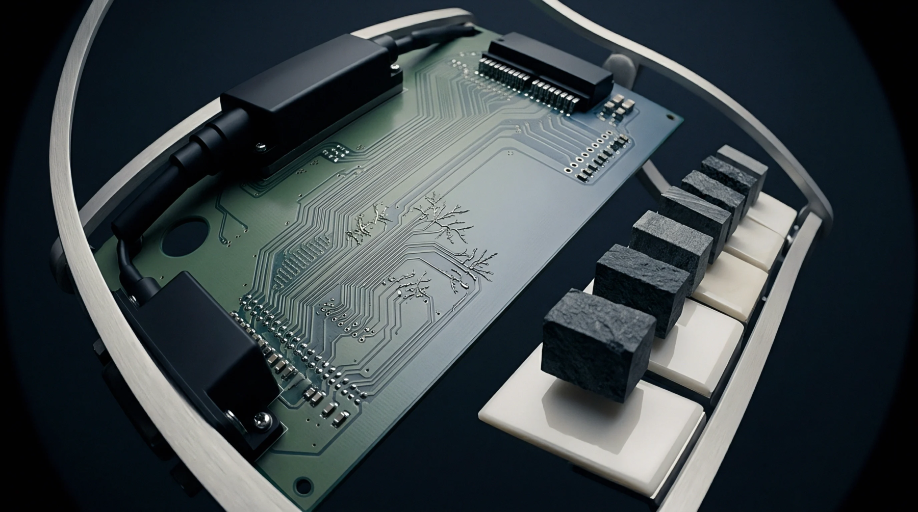
Dynamic phase calibration models calculate coupled thermal permittivity and physical expansion shifts to eliminate skew across heterogeneous interconnect stackups.
Evaluating in-plane permittivity accounts for horizontal field concentration in edge-coupled pairs, preventing 2 to 5 ohm impedance drops in high-density boards.
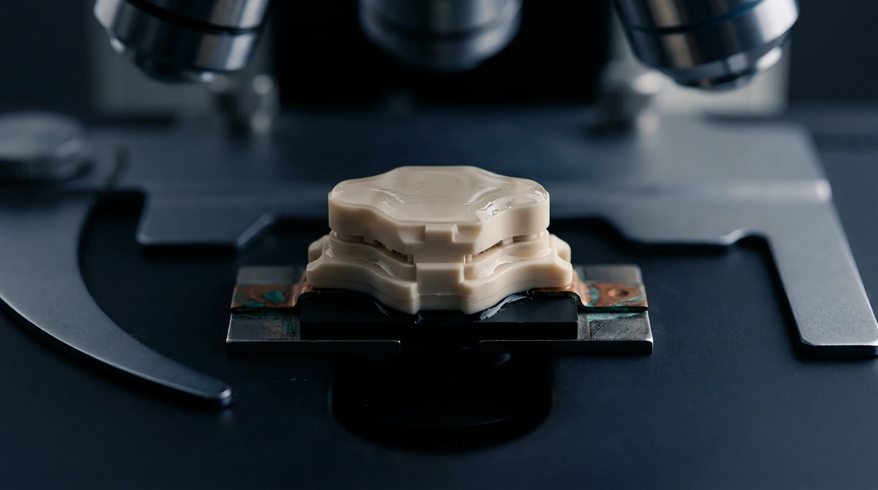
Spatial dielectric variation across organic package cores causes differential phase skew and impedance ripple, requiring spread glass and strict panel-level metrology.
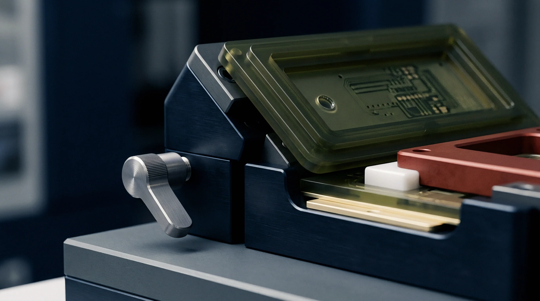
Quantify anisotropic permittivity drift by extracting tensor components across environmental chambers to preserve differential impedance and phase margins.
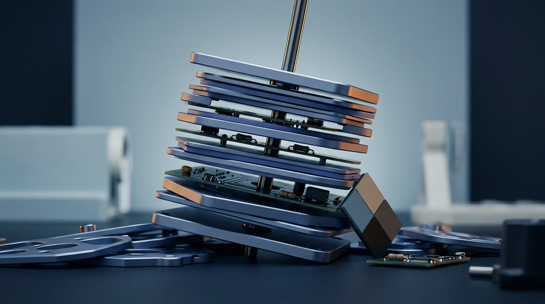
Glass reinforcement drives in-plane permittivity up to fifteen percent above out-of-plane values, demanding dual-axis coupon extraction for RF designs.
Clamped stripline resonators extract out-of-plane permittivity and loss tangent up to 10 GHz by measuring resonant modes of unclad dielectric sheets under pressure.
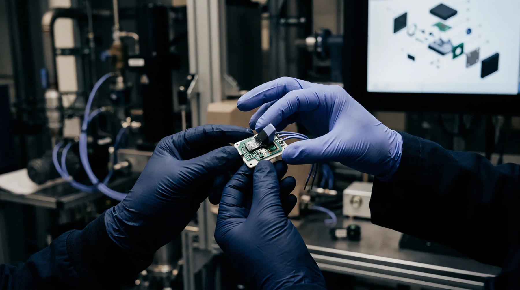
Mitigate differential stripline glass weave skew by combining low-Dk spread glass, multi-ply prepregs, and minimum two-degree routing offsets on drawings.
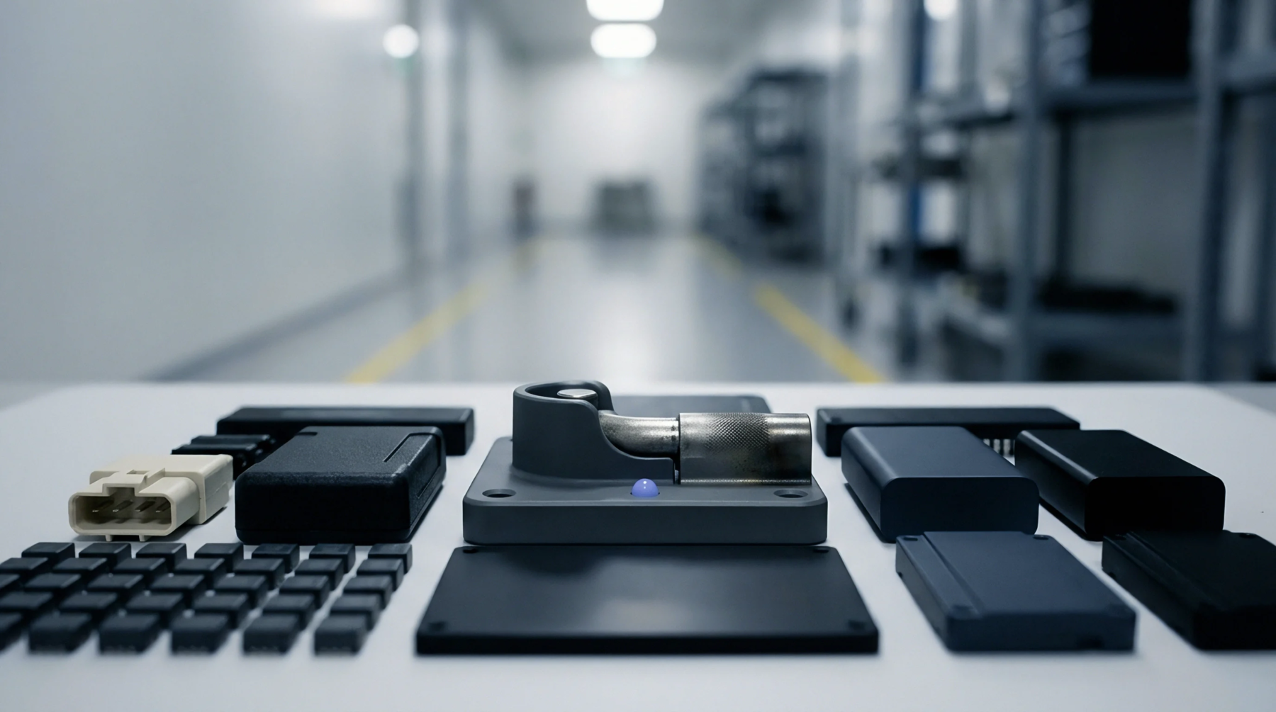
Trapezoidal trace tapering reduces effective line width, raising microstrip impedance above rectangular model predictions and demanding field solver validation.
Interfacial water accumulation increases submillimeter dielectric loss tangents, demanding fluoropolymer or LCP resins with hydrolytically stable silane couples.

Copper foil roughness profiles dominate gigahertz conductor loss, causing up to forty percent attenuation variations across equivalent IPC-4101 slash sheets.

Specifying mechanically spread low-Dk glass styles in dual-ply prepreg constructions eliminates intra-pair skew while preserving standard panel utilization.
Differential phase skew sensitivity to glass yarn spacing requires spread-weave fabrics or Low-Dk fibers to suppress localized trace-to-resin permittivity mismatch.
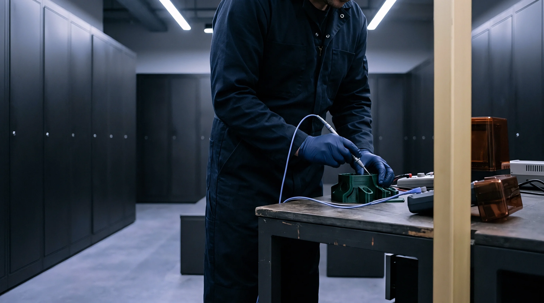
Hydrocarbon laminates recover nominal dielectric constants within hours through Fickian desorption, accelerated by post-reflow baking at 105 degrees Celsius.
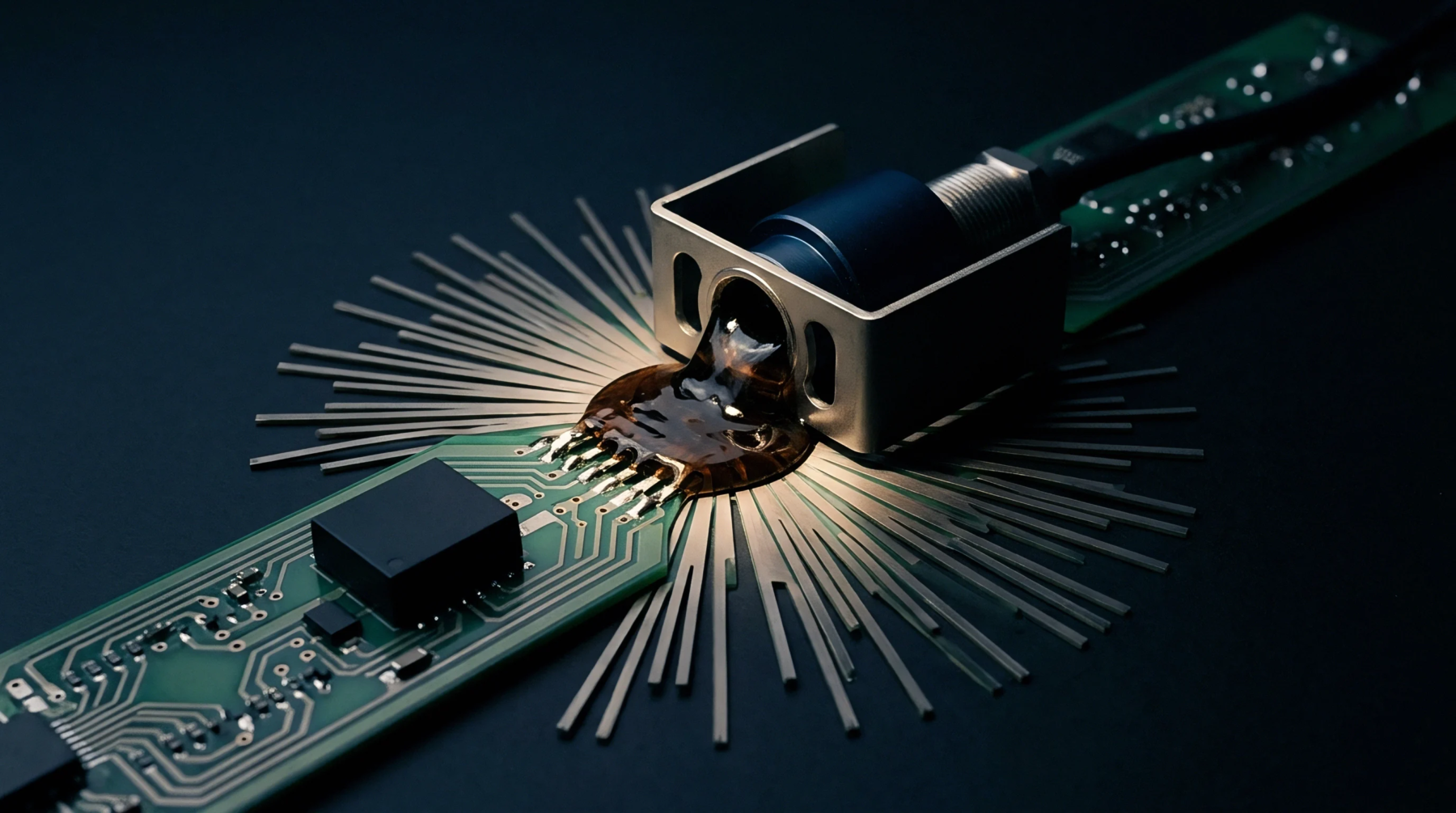
Vacuum lamination compacts copper tooth profiles and redistributes resin fractions, escalating high-frequency insertion loss far beyond datasheet values.
Specify mechanically spread low-Dk glass fabrics and restrict prepreg substitution in fabrication drawings to control high-frequency phase skew and panel cost.
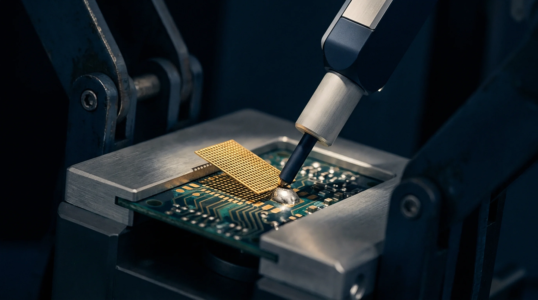
Glass bundle heterogeneity induces differential phase skew that requires spread cloth styles, trace angling, or low-Dk glass to maintain channel eye closure.
Bare PCB dielectric constant discrepancies stem from test fixture air gaps, glass weave density, and copper tooth profile, requiring effective Dk modeling.
Mechanically spread glass fabrics eliminate open resin windows, stabilizing spatial dielectric permittivity to control high-frequency trace impedance and phase skew.
Expertise is a utility, not a secret. sentiention™ publishes its working knowledge as open reference: intelligence layer covering the materials it sources, the markets it enters, and the reference that serves both.